
Engineering Mechanics: Statics & Dynamics (14th Edition)
14th Edition
ISBN: 9780133915426
Author: Russell C. Hibbeler
Publisher: PEARSON
expand_more
expand_more
format_list_bulleted
Concept explainers
Videos
Textbook Question
Chapter 7.2, Problem 62P
The beam will fail when the maximum internal moment is Mmax. Determine the position x of the concentrated force P and its smallest magnitude that will cause failure.
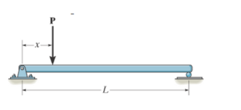
Prob. 7–62
Expert Solution & Answer
Want to see the full answer?
Check out a sample textbook solution
Students have asked these similar questions
Find the support reactions at the fixed support
O. The beam has a mass of 500 kg, and it has a uniform cross section.
1.2 m
A
1.4 kN
1.8 m
15 kN.m
B
●
1.8 m
30°
3 kN
x
Solve using equilibrium equations and provide explanation (FBD should be included)
The shaft is supported by a journal bearing at A and a thrust
bearing at B. Determine the normal force, shear force and moment
at a section passing through (a) point C, which is just to right of
bearing at A, and (b) point D, which is just to the left of the Force F2.
Given:
F1 =
= 2.5 kip
F2 = 3 kip
lb
W = 75
ft
-
b = 12 ft
c = 2 ft
a = 6 ft
F2
D
a
b
Chapter 7 Solutions
Engineering Mechanics: Statics & Dynamics (14th Edition)
Ch. 7.1 - In each case, calculate the reaction at A and then...Ch. 7.1 - Determine the normal force, shear force, and...Ch. 7.1 - Determine the normal force, shear force, and...Ch. 7.1 - Determine the normal force, shear force, and...Ch. 7.1 - Determine the normal force, shear force, and...Ch. 7.1 - Determine the normal force, shear force, and...Ch. 7.1 - Determine the normal force, shear force, and...Ch. 7.1 - Determine the shear force and moment at points C...Ch. 7.1 - Determine the internal normal force and shear...Ch. 7.1 - Two beams are attached to the column such that...
Ch. 7.1 - The beam weighs 280 lb/ft. Determine the internal...Ch. 7.1 - The pliers are used to grip the tube at B. If a...Ch. 7.1 - Determine the distance a as a fraction of the...Ch. 7.1 - Determine the internal shear force and moment...Ch. 7.1 - Determine the internal shear force and moment...Ch. 7.1 - Determine the normal force, shear force, and...Ch. 7.1 - The cable will fail when subjected to a tension of...Ch. 7.1 - Determine the internal normal force, shear force,...Ch. 7.1 - Determine the distance a between the bearings in...Ch. 7.1 - Determine the internal normal force, shear force,...Ch. 7.1 - The shaft is supported by a journal bearing at A...Ch. 7.1 - Determine the internal normal force, shear force,...Ch. 7.1 - Determine the internal normal force, shear force,...Ch. 7.1 - The cantilevered rack is used to support each end...Ch. 7.1 - Determine the internal normal force, shear force,...Ch. 7.1 - Determine the internal normal force, shear force,...Ch. 7.1 - Rod AB is fixed to a smooth collar D, which slides...Ch. 7.1 - Determine the internal normal force, shear force,...Ch. 7.1 - Determine the internal normal force, shear force,...Ch. 7.1 - Determine the internal normal force, shear force,...Ch. 7.1 - Determine the ratio of a/b for which the shear...Ch. 7.1 - Determine the normal force, shear force, and...Ch. 7.1 - Determine the internal normal force, shear force,...Ch. 7.1 - Determine the internal normal force, shear force,...Ch. 7.1 - Determine the internal normal force, shear force,...Ch. 7.1 - Determine the normal force, shear force, and...Ch. 7.1 - Determine the normal force, shear force, and...Ch. 7.1 - Determine the internal normal force, shear force,...Ch. 7.1 - Determine the internal normal force, shear force,...Ch. 7.1 - Determine the internal normal force, shear force,...Ch. 7.1 - Determine the internal normal force, shear force,...Ch. 7.1 - The strongback or lifting beam is used for...Ch. 7.1 - Determine the internal normal force, shear force,...Ch. 7.1 - Determine the internal normal force, shear force,...Ch. 7.1 - Determine the internal normal force, shear force,...Ch. 7.1 - The distributed loading W = W0 sin , measured per...Ch. 7.1 - Solve Prob. 7-39 for = 120. Probs. 739/40Ch. 7.1 - Determine the x, y. z components of force and...Ch. 7.1 - Determine the x, y, z components of force and...Ch. 7.1 - Determine the x, y, z components of internal...Ch. 7.1 - Determine the x, y. z components of internal...Ch. 7.2 - Determine the shear and moment as a function of x,...Ch. 7.2 - Determine the shear and moment as a function of x,...Ch. 7.2 - Determine the shear and moment as a function of x,...Ch. 7.2 - Determine the shear and moment as a function of x,...Ch. 7.2 - Determine the shear and moment as a function of x,...Ch. 7.2 - Determine the shear and moment as a function of x,...Ch. 7.2 - Draw the shear and moment diagrams for the shaft...Ch. 7.2 - Draw the shear and moment diagrams for the beam...Ch. 7.2 - Draw the shear and moment diagrams for the beam...Ch. 7.2 - Draw the shear and moment diagrams for the...Ch. 7.2 - Draw the shear and moment diagrams of the beam (a)...Ch. 7.2 - If L = 9 m, the beam will fail when the maximum...Ch. 7.2 - Draw the shear and moment diagrams for the beam....Ch. 7.2 - Draw the shear and moment diagrams for the beam....Ch. 7.2 - Draw the shear and bending-moment diagrams for the...Ch. 7.2 - The shaft is supported by a smooth thrust bearing...Ch. 7.2 - Draw the shear and moment diagrams for the beam....Ch. 7.2 - Draw the shear and moment diagrams for the beam....Ch. 7.2 - Draw the shear and moment diagrams for the...Ch. 7.2 - Draw the shear and bending-moment diagrams for...Ch. 7.2 - Draw the shear and moment diagrams for the beam....Ch. 7.2 - The shaft is supported by a smooth thrust bearing...Ch. 7.2 - Draw the shear and moment diagrams for the beam....Ch. 7.2 - The beam will fail when the maximum internal...Ch. 7.2 - Prob. 63PCh. 7.2 - Prob. 64PCh. 7.2 - Prob. 65PCh. 7.2 - Draw the shear and moment diagrams for the beam....Ch. 7.2 - Determine the internal normal force, shear force,...Ch. 7.2 - The quarter circular rod lies in the horizontal...Ch. 7.2 - Express the internal shear and moment components...Ch. 7.3 - Draw the shear and moment diagrams for the beam....Ch. 7.3 - Draw the shear and moment diagrams for the beam....Ch. 7.3 - Draw the shear and moment diagrams for the beam....Ch. 7.3 - Draw the shear and moment diagrams for the beam....Ch. 7.3 - Draw the shear and moment diagrams for the beam....Ch. 7.3 - Draw the shear and moment diagrams for the beam....Ch. 7.3 - Draw the shear and moment diagrams for the beam....Ch. 7.3 - Draw the shear and moment diagrams for the beam....Ch. 7.3 - Draw the shear and moment diagrams for the beam....Ch. 7.3 - Draw the shear and moment diagrams for the...Ch. 7.3 - Draw the shear and moment diagrams for the beam....Ch. 7.3 - Draw the shear and moment diagrams for the beam....Ch. 7.3 - Draw the shear and moment diagrams for the beam....Ch. 7.3 - Draw the shear and moment diagrams for the beam....Ch. 7.3 - Draw the shear and moment diagrams for the beam....Ch. 7.3 - Draw the shear and moment diagrams for the shaft....Ch. 7.3 - Draw the shear and moment diagrams for the beam....Ch. 7.3 - The beam consists of three segments pin connected...Ch. 7.3 - Draw the shear and moment diagrams for the beam....Ch. 7.3 - Draw the shear and moment diagrams for the beam....Ch. 7.3 - Draw the shear and moment diagrams for the beam....Ch. 7.3 - Draw the shear and moment diagrams for the beam....Ch. 7.3 - Draw the shear and moment diagrams for the beam....Ch. 7.3 - Draw the shear and moment diagrams for the beam....Ch. 7.3 - Draw the shear and moment diagrams for the beam....Ch. 7.3 - Draw the shear and moment diagrams for the beam....Ch. 7.3 - Draw the shear and moment diagrams for the beam....Ch. 7.3 - Draw the shear and moment diagrams for the beam....Ch. 7.3 - Draw the shear and moment diagrams for the beam....Ch. 7.3 - Draw the shear and moment diagrams for the beam....Ch. 7.4 - The cable supports the three loads shown....Ch. 7.4 - Prob. 95PCh. 7.4 - Determine the tension in each segment of the cable...Ch. 7.4 - Prob. 97PCh. 7.4 - The cable supports the loading shown. Determine...Ch. 7.4 - The cable supports the three loads shown....Ch. 7.4 - The cable supports the three loads shown....Ch. 7.4 - Determine the force P needed to hold the cable in...Ch. 7.4 - Determine the maximum uniform loading w, measured...Ch. 7.4 - The cable is subjected to a uniform loading of w =...Ch. 7.4 - The cable AB is subjected to a uniform loading of...Ch. 7.4 - If x = 2 ft and the crate weighs 300 lb, which...Ch. 7.4 - If yB = 1.5 ft. determine the largest weight of...Ch. 7.4 - The cable supports a girder which weighs 850...Ch. 7.4 - The cable is subjected to a uniform loading of w =...Ch. 7.4 - If the pipe has a mass per unit length of 1500...Ch. 7.4 - Prob. 110PCh. 7.4 - Prob. 111PCh. 7.4 - The cable will break when the maximum tension...Ch. 7.4 - Prob. 113PCh. 7.4 - The power transmission cable weighs 10 lb/fl. If...Ch. 7.4 - Prob. 115PCh. 7.4 - Prob. 116PCh. 7.4 - Prob. 117PCh. 7.4 - Prob. 118PCh. 7.4 - Show that the deflection curve of the cable...Ch. 7.4 - Prob. 120PCh. 7.4 - Prob. 121PCh. 7.4 - Prob. 122PCh. 7.4 - A cable has a weight of 5 lb/ft. If it can span...Ch. 7.4 - The 10 kg/m cable is suspended between the...Ch. 7.4 - Determine the internal normal force, shear force,...Ch. 7.4 - Prob. 2RPCh. 7.4 - Prob. 3RPCh. 7.4 - Prob. 4RPCh. 7.4 - Draw the shear and moment diagrams for the beam....Ch. 7.4 - A chain is suspended between points at the same...
Knowledge Booster


Learn more about
Need a deep-dive on the concept behind this application? Look no further. Learn more about this topic, mechanical-engineering and related others by exploring similar questions and additional content below.Similar questions
- Free body diagram and explanation must be includedarrow_forward7-8. Determine the internal shear force and moment acting at point Cin the beam. 900 lb - ft 500 Ib/ft 900 Ib - ft A 61 -3 ft- Prob. 7-8arrow_forward7-11. Determine the internal normal force, shear force, and moment at points C and D of the beam. 60 lb/ft 12 ft Prob. 7-10 15 ft 40 lb/ft _B Prob. 7-11 ID -5 ft- -10 ft 690 lb 13/12arrow_forward
- 7-10. The cable will fail when subjected to a tension of 2 kN. Determine the largest vertical load P the frame will support and calculate the internal normal force, shear force, and moment at a section passing through point C for this loading. B 0.1 m 0.5 m C -0.75 m- -0.75 m -0.75 m- Parrow_forwardThe magnitude of the triangular distributed load is w0 = 2 kN/m. Determine the internal forces and moment at A.arrow_forwardDetermine the moment MAB produced by the force F shown in the figure which tends to rotate the bar about the axis AB.arrow_forward
- The tapered beam supports the concentrated force P at its center. Determine the absolute maximum bending stress in the beam. The reactions at the supports are vertical. Toarrow_forwardFI-6. Determine the resultant internal normal force, shear force, and bending moment at point Cin the beam. 5 KN /marrow_forwardDetermine the maximum moment at point C on the single girder caused by the moving dolly that has a mass of 2 Mg and a mass center at G. Assume A is a roller.arrow_forward
- The shaft assembly is supported by two smooth journal bearings A and B and a short link DC. If a couple moment is shown, components of force reaction at the journal bearings and 20 120 mm applied to the shaft as determine the the force in the link. The link lies 250 mm 300 mm in a plane parallel to the y-z plane and the bearings are properly aligned on the shaft. 250 N m 400 mmarrow_forwardAforce of magnitude P = 166 N is applied to the stationary machine handle as shown. Write the force and moment reactions at O as vectors. Neglect the weight of the handle assembly. A P 12° 125 mm 165 mm -y Answers: R = ( -162.37 i+ -0 j+ -34.51 k)N M = ( i i+ i j+ i k) N-marrow_forwardThe answer is F = 4.56 kN but I am unsure of how to get there.arrow_forward
arrow_back_ios
SEE MORE QUESTIONS
arrow_forward_ios
Recommended textbooks for you
 Elements Of ElectromagneticsMechanical EngineeringISBN:9780190698614Author:Sadiku, Matthew N. O.Publisher:Oxford University Press
 Mechanics of Materials (10th Edition)Mechanical EngineeringISBN:9780134319650Author:Russell C. HibbelerPublisher:PEARSON
 Thermodynamics: An Engineering ApproachMechanical EngineeringISBN:9781259822674Author:Yunus A. Cengel Dr., Michael A. BolesPublisher:McGraw-Hill Education
 Control Systems EngineeringMechanical EngineeringISBN:9781118170519Author:Norman S. NisePublisher:WILEY
 Mechanics of Materials (MindTap Course List)Mechanical EngineeringISBN:9781337093347Author:Barry J. Goodno, James M. GerePublisher:Cengage Learning
 Engineering Mechanics: StaticsMechanical EngineeringISBN:9781118807330Author:James L. Meriam, L. G. Kraige, J. N. BoltonPublisher:WILEY
Elements Of Electromagnetics
Mechanical Engineering
ISBN:9780190698614
Author:Sadiku, Matthew N. O.
Publisher:Oxford University Press
Mechanics of Materials (10th Edition)
Mechanical Engineering
ISBN:9780134319650
Author:Russell C. Hibbeler
Publisher:PEARSON
Thermodynamics: An Engineering Approach
Mechanical Engineering
ISBN:9781259822674
Author:Yunus A. Cengel Dr., Michael A. Boles
Publisher:McGraw-Hill Education
Control Systems Engineering
Mechanical Engineering
ISBN:9781118170519
Author:Norman S. Nise
Publisher:WILEY
Mechanics of Materials (MindTap Course List)
Mechanical Engineering
ISBN:9781337093347
Author:Barry J. Goodno, James M. Gere
Publisher:Cengage Learning
Engineering Mechanics: Statics
Mechanical Engineering
ISBN:9781118807330
Author:James L. Meriam, L. G. Kraige, J. N. Bolton
Publisher:WILEY
Everything About COMBINED LOADING in 10 Minutes! Mechanics of Materials; Author: Less Boring Lectures;https://www.youtube.com/watch?v=N-PlI900hSg;License: Standard youtube license