
Engineering Mechanics: Statics & Dynamics (14th Edition)
14th Edition
ISBN: 9780133915426
Author: Russell C. Hibbeler
Publisher: PEARSON
expand_more
expand_more
format_list_bulleted
Concept explainers
Videos
Textbook Question
Chapter 7.1, Problem 43P
Determine the x, y, z components of internal loading at a section passing through point B in the pipe assembly. Neglect the weight of the pipe. Take F1 ={200i − 100j − 400k}N and F2 = {300i − 500k}N.
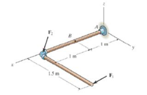
Prob. 7–43
Expert Solution & Answer
Want to see the full answer?
Check out a sample textbook solution
Students have asked these similar questions
Determine the reaction force acting on the beam AB, given F = 680 N.
5
4
4 m
3
3
A
B
30°
3 m
F (N)
The frame in the figure is made of an HEA 300 profile (E = 210 GPa, material S355).a) Determine the support reactions at point A. (1p)b) Sketch the bending moment diagram caused by the loading. (1p)c) Using the principle of virtual work (unit load method), calculate the vertical displacement at point B using moment diagrams. Also take into account the compression of the column. (3p)
9 kN/m
6 kN/m
3 m
6 m
Bestäm, med hjälp av friläggning och jämviktsberäkningar, tvärkrafts- och momentdiagram
för balken i figuren. Extrempunkter ska anges med både läge och värde.
Chapter 7 Solutions
Engineering Mechanics: Statics & Dynamics (14th Edition)
Ch. 7.1 - In each case, calculate the reaction at A and then...Ch. 7.1 - Determine the normal force, shear force, and...Ch. 7.1 - Determine the normal force, shear force, and...Ch. 7.1 - Determine the normal force, shear force, and...Ch. 7.1 - Determine the normal force, shear force, and...Ch. 7.1 - Determine the normal force, shear force, and...Ch. 7.1 - Determine the normal force, shear force, and...Ch. 7.1 - Determine the shear force and moment at points C...Ch. 7.1 - Determine the internal normal force and shear...Ch. 7.1 - Two beams are attached to the column such that...
Ch. 7.1 - The beam weighs 280 lb/ft. Determine the internal...Ch. 7.1 - The pliers are used to grip the tube at B. If a...Ch. 7.1 - Determine the distance a as a fraction of the...Ch. 7.1 - Determine the internal shear force and moment...Ch. 7.1 - Determine the internal shear force and moment...Ch. 7.1 - Determine the normal force, shear force, and...Ch. 7.1 - The cable will fail when subjected to a tension of...Ch. 7.1 - Determine the internal normal force, shear force,...Ch. 7.1 - Determine the distance a between the bearings in...Ch. 7.1 - Determine the internal normal force, shear force,...Ch. 7.1 - The shaft is supported by a journal bearing at A...Ch. 7.1 - Determine the internal normal force, shear force,...Ch. 7.1 - Determine the internal normal force, shear force,...Ch. 7.1 - The cantilevered rack is used to support each end...Ch. 7.1 - Determine the internal normal force, shear force,...Ch. 7.1 - Determine the internal normal force, shear force,...Ch. 7.1 - Rod AB is fixed to a smooth collar D, which slides...Ch. 7.1 - Determine the internal normal force, shear force,...Ch. 7.1 - Determine the internal normal force, shear force,...Ch. 7.1 - Determine the internal normal force, shear force,...Ch. 7.1 - Determine the ratio of a/b for which the shear...Ch. 7.1 - Determine the normal force, shear force, and...Ch. 7.1 - Determine the internal normal force, shear force,...Ch. 7.1 - Determine the internal normal force, shear force,...Ch. 7.1 - Determine the internal normal force, shear force,...Ch. 7.1 - Determine the normal force, shear force, and...Ch. 7.1 - Determine the normal force, shear force, and...Ch. 7.1 - Determine the internal normal force, shear force,...Ch. 7.1 - Determine the internal normal force, shear force,...Ch. 7.1 - Determine the internal normal force, shear force,...Ch. 7.1 - Determine the internal normal force, shear force,...Ch. 7.1 - The strongback or lifting beam is used for...Ch. 7.1 - Determine the internal normal force, shear force,...Ch. 7.1 - Determine the internal normal force, shear force,...Ch. 7.1 - Determine the internal normal force, shear force,...Ch. 7.1 - The distributed loading W = W0 sin , measured per...Ch. 7.1 - Solve Prob. 7-39 for = 120. Probs. 739/40Ch. 7.1 - Determine the x, y. z components of force and...Ch. 7.1 - Determine the x, y, z components of force and...Ch. 7.1 - Determine the x, y, z components of internal...Ch. 7.1 - Determine the x, y. z components of internal...Ch. 7.2 - Determine the shear and moment as a function of x,...Ch. 7.2 - Determine the shear and moment as a function of x,...Ch. 7.2 - Determine the shear and moment as a function of x,...Ch. 7.2 - Determine the shear and moment as a function of x,...Ch. 7.2 - Determine the shear and moment as a function of x,...Ch. 7.2 - Determine the shear and moment as a function of x,...Ch. 7.2 - Draw the shear and moment diagrams for the shaft...Ch. 7.2 - Draw the shear and moment diagrams for the beam...Ch. 7.2 - Draw the shear and moment diagrams for the beam...Ch. 7.2 - Draw the shear and moment diagrams for the...Ch. 7.2 - Draw the shear and moment diagrams of the beam (a)...Ch. 7.2 - If L = 9 m, the beam will fail when the maximum...Ch. 7.2 - Draw the shear and moment diagrams for the beam....Ch. 7.2 - Draw the shear and moment diagrams for the beam....Ch. 7.2 - Draw the shear and bending-moment diagrams for the...Ch. 7.2 - The shaft is supported by a smooth thrust bearing...Ch. 7.2 - Draw the shear and moment diagrams for the beam....Ch. 7.2 - Draw the shear and moment diagrams for the beam....Ch. 7.2 - Draw the shear and moment diagrams for the...Ch. 7.2 - Draw the shear and bending-moment diagrams for...Ch. 7.2 - Draw the shear and moment diagrams for the beam....Ch. 7.2 - The shaft is supported by a smooth thrust bearing...Ch. 7.2 - Draw the shear and moment diagrams for the beam....Ch. 7.2 - The beam will fail when the maximum internal...Ch. 7.2 - Prob. 63PCh. 7.2 - Prob. 64PCh. 7.2 - Prob. 65PCh. 7.2 - Draw the shear and moment diagrams for the beam....Ch. 7.2 - Determine the internal normal force, shear force,...Ch. 7.2 - The quarter circular rod lies in the horizontal...Ch. 7.2 - Express the internal shear and moment components...Ch. 7.3 - Draw the shear and moment diagrams for the beam....Ch. 7.3 - Draw the shear and moment diagrams for the beam....Ch. 7.3 - Draw the shear and moment diagrams for the beam....Ch. 7.3 - Draw the shear and moment diagrams for the beam....Ch. 7.3 - Draw the shear and moment diagrams for the beam....Ch. 7.3 - Draw the shear and moment diagrams for the beam....Ch. 7.3 - Draw the shear and moment diagrams for the beam....Ch. 7.3 - Draw the shear and moment diagrams for the beam....Ch. 7.3 - Draw the shear and moment diagrams for the beam....Ch. 7.3 - Draw the shear and moment diagrams for the...Ch. 7.3 - Draw the shear and moment diagrams for the beam....Ch. 7.3 - Draw the shear and moment diagrams for the beam....Ch. 7.3 - Draw the shear and moment diagrams for the beam....Ch. 7.3 - Draw the shear and moment diagrams for the beam....Ch. 7.3 - Draw the shear and moment diagrams for the beam....Ch. 7.3 - Draw the shear and moment diagrams for the shaft....Ch. 7.3 - Draw the shear and moment diagrams for the beam....Ch. 7.3 - The beam consists of three segments pin connected...Ch. 7.3 - Draw the shear and moment diagrams for the beam....Ch. 7.3 - Draw the shear and moment diagrams for the beam....Ch. 7.3 - Draw the shear and moment diagrams for the beam....Ch. 7.3 - Draw the shear and moment diagrams for the beam....Ch. 7.3 - Draw the shear and moment diagrams for the beam....Ch. 7.3 - Draw the shear and moment diagrams for the beam....Ch. 7.3 - Draw the shear and moment diagrams for the beam....Ch. 7.3 - Draw the shear and moment diagrams for the beam....Ch. 7.3 - Draw the shear and moment diagrams for the beam....Ch. 7.3 - Draw the shear and moment diagrams for the beam....Ch. 7.3 - Draw the shear and moment diagrams for the beam....Ch. 7.3 - Draw the shear and moment diagrams for the beam....Ch. 7.4 - The cable supports the three loads shown....Ch. 7.4 - Prob. 95PCh. 7.4 - Determine the tension in each segment of the cable...Ch. 7.4 - Prob. 97PCh. 7.4 - The cable supports the loading shown. Determine...Ch. 7.4 - The cable supports the three loads shown....Ch. 7.4 - The cable supports the three loads shown....Ch. 7.4 - Determine the force P needed to hold the cable in...Ch. 7.4 - Determine the maximum uniform loading w, measured...Ch. 7.4 - The cable is subjected to a uniform loading of w =...Ch. 7.4 - The cable AB is subjected to a uniform loading of...Ch. 7.4 - If x = 2 ft and the crate weighs 300 lb, which...Ch. 7.4 - If yB = 1.5 ft. determine the largest weight of...Ch. 7.4 - The cable supports a girder which weighs 850...Ch. 7.4 - The cable is subjected to a uniform loading of w =...Ch. 7.4 - If the pipe has a mass per unit length of 1500...Ch. 7.4 - Prob. 110PCh. 7.4 - Prob. 111PCh. 7.4 - The cable will break when the maximum tension...Ch. 7.4 - Prob. 113PCh. 7.4 - The power transmission cable weighs 10 lb/fl. If...Ch. 7.4 - Prob. 115PCh. 7.4 - Prob. 116PCh. 7.4 - Prob. 117PCh. 7.4 - Prob. 118PCh. 7.4 - Show that the deflection curve of the cable...Ch. 7.4 - Prob. 120PCh. 7.4 - Prob. 121PCh. 7.4 - Prob. 122PCh. 7.4 - A cable has a weight of 5 lb/ft. If it can span...Ch. 7.4 - The 10 kg/m cable is suspended between the...Ch. 7.4 - Determine the internal normal force, shear force,...Ch. 7.4 - Prob. 2RPCh. 7.4 - Prob. 3RPCh. 7.4 - Prob. 4RPCh. 7.4 - Draw the shear and moment diagrams for the beam....Ch. 7.4 - A chain is suspended between points at the same...
Knowledge Booster


Learn more about
Need a deep-dive on the concept behind this application? Look no further. Learn more about this topic, mechanical-engineering and related others by exploring similar questions and additional content below.Similar questions
- B C 3.0 E F G 40 kN [m] 3.0 3.0 3.0 Fackverket belastas med en punktlast i G enligt figuren. Bestäm normalkraften i stängerna BC, BF och EF.arrow_forwardL q=8 kN/m P= 12 kN En stång belastas av en punklast P vid sin ena ände samt av en jämnt utbredd last q längs hela sin längd. Stången har en tvärsnittsarea A = 150 mm² och är tillverkad av stål med elasticitetsmodul E-210 GPa. Stångens längd, i sitt obelastade tillstånd, är Z-3 m. a) Hur stor är den största normalspänning som uppstår i stången? b) Hur stor blir förlängningen av stången, orsakad av lasterna P och q?arrow_forwardA turbocharged engine with a compression ratio of 8 is being designed using an air standard cycle. The ambient air is assumed to be 300K and 100 kPa. The temperature at the end of the compression in the cylinder is desired to be 1000K, assuming no combustion prior to reaching TDC. At the end of the cylinder expansion the temperature is also desired to be 1000K. If both the turbine and the compressor have mechanical efficiencies of 80%, what will be the pressure ratio of the compressor and what will be the turbine exhaust temperature?arrow_forward
- Q6: A turbocharged engine with a compression ratio of 8 is being designed using an air standard cycle. The ambient air is assumed to be 300K and 100 kPa. The temperature at the end of the compression in the cylinder is desired to be 1000K, assuming no combustion prior to reaching TDC. At the end of the cylinder expansion the temperature is also desired to be 1000K. If both the turbine and the compressor have mechanical efficiencies of 80%, what will be the pressure ratio of the compressor and what will be the turbine exhaust temperature?arrow_forwardQ5: A 5.6 litre V8 engine with a compression ratio of 9.4:1 operates on an air-standard Otto cycle at 2800 RPM, with a volumetric efficiency of 90 % and a stoichiometric air-fuel ratio using gasoline. The exhaust flow undergoes a temperature drop of 44ºC as it passes through the turbine of the supercharger. Calculate (a) mass flow rate of exhaust gas and (b) power available to drive the turbocharger compressor.arrow_forwarddo handwrittenarrow_forward
- Create a report: An example of two people who do not understand each other due to lack of communication, and mention ways to resolve the issue between them .arrow_forwardI want the kinematic diagram to be draw like this plsarrow_forwardAccording to the principles and steps above, draw the kinematic diagram of following mechanisms. Mark the appropriate scale, calculates the degree of freedom. NO.1 NO.2 NO: 3 NO.: 4arrow_forward
- An office building is planned with a lateral-force-resisting system designed for earthquake resistance in aseismic zone. The seismic capacity of the proposed system, expressed as a force factor, is assumed tofollow a lognormal distribution with a median of 6.5 and a standard deviation of 1.5. The ground motionfrom the largest expected earthquake at the site is estimated to correspond to an equivalent force factor of 5.5.(a) What is the estimated probability that the building will experience damage when subjected to the largest expected earthquake? (b) If the building survives (i.e., experiences no damage) during a previous moderate earthquake with aforce factor of 4.0, what is the updated probability of failure of the building under the largest expectedearthquake?(c) Suppose future occurrences of the largest expected earthquake follow a Poisson process with a mean return period of 500 years. Assuming that damage events from different earthquakes are statisticallyindependent,…arrow_forwardDuring a plant visit, it was noticed that a 12-m-long section of a 10-cm-diameter steam pipe is completely exposed to the ambient air. The temperature measurements indicate that the average temperature of the outer surface of the steam pipe is 75°C when the ambient temperature is 5°C. There are also light winds in the area at 10 km/h. The emissivity of the outer surface of the pipe is 0.8, and the average temperature of the surfaces surrounding the pipe, including the sky, is estimated to be 0°C. Determine the amount of heat lost from the steam during a 10-h-long work day. Steam is supplied by a gas-fired steam generator that has an efficiency of 80 percent, and the plant pays $1.05/therm of natural gas. If the pipe is insulated and 90 percent of the heat loss is saved, determine the amount of money this facility will save a year as a result of insulating the steam pipes. Assume the plant operates every day of the year for 10 h. State your assumptions.arrow_forwardAn old fashioned ice cream kit consists of two concentric cylinders of radii Ra and Rb. The inner cylinder is filled with milk and ice cream ingredients while the space between the two cylinders is filled with an ice-brine mixture. Ice cream begins to form on the inner surface of the inner cylinder. To expedite the process, would you recommend rotating the inner cylinder? Justify your recommendation. icecream/ ice-brine Ra Rbarrow_forward
arrow_back_ios
SEE MORE QUESTIONS
arrow_forward_ios
Recommended textbooks for you
 Elements Of ElectromagneticsMechanical EngineeringISBN:9780190698614Author:Sadiku, Matthew N. O.Publisher:Oxford University Press
 Mechanics of Materials (10th Edition)Mechanical EngineeringISBN:9780134319650Author:Russell C. HibbelerPublisher:PEARSON
 Thermodynamics: An Engineering ApproachMechanical EngineeringISBN:9781259822674Author:Yunus A. Cengel Dr., Michael A. BolesPublisher:McGraw-Hill Education
 Control Systems EngineeringMechanical EngineeringISBN:9781118170519Author:Norman S. NisePublisher:WILEY
 Mechanics of Materials (MindTap Course List)Mechanical EngineeringISBN:9781337093347Author:Barry J. Goodno, James M. GerePublisher:Cengage Learning
 Engineering Mechanics: StaticsMechanical EngineeringISBN:9781118807330Author:James L. Meriam, L. G. Kraige, J. N. BoltonPublisher:WILEY
Elements Of Electromagnetics
Mechanical Engineering
ISBN:9780190698614
Author:Sadiku, Matthew N. O.
Publisher:Oxford University Press
Mechanics of Materials (10th Edition)
Mechanical Engineering
ISBN:9780134319650
Author:Russell C. Hibbeler
Publisher:PEARSON
Thermodynamics: An Engineering Approach
Mechanical Engineering
ISBN:9781259822674
Author:Yunus A. Cengel Dr., Michael A. Boles
Publisher:McGraw-Hill Education
Control Systems Engineering
Mechanical Engineering
ISBN:9781118170519
Author:Norman S. Nise
Publisher:WILEY
Mechanics of Materials (MindTap Course List)
Mechanical Engineering
ISBN:9781337093347
Author:Barry J. Goodno, James M. Gere
Publisher:Cengage Learning
Engineering Mechanics: Statics
Mechanical Engineering
ISBN:9781118807330
Author:James L. Meriam, L. G. Kraige, J. N. Bolton
Publisher:WILEY
Types Of loads - Engineering Mechanics | Abhishek Explained; Author: Prime Course;https://www.youtube.com/watch?v=4JVoL9wb5yM;License: Standard YouTube License, CC-BY