
Engineering Mechanics: Statics & Dynamics (14th Edition)
14th Edition
ISBN: 9780133915426
Author: Russell C. Hibbeler
Publisher: PEARSON
expand_more
expand_more
format_list_bulleted
Concept explainers
Videos
Textbook Question
Chapter 7.4, Problem 106P
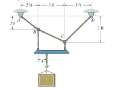
If yB = 1.5 ft. determine the largest weight of the crate and its placement x so that neither cable segment AB, BC, or CD is subjected to a tension that exceeds 200 lb.
Probs. 7–105/106
Expert Solution & Answer
Want to see the full answer?
Check out a sample textbook solution
Students have asked these similar questions
Two large tanks, each holding 100 L of liquid, are interconnected by pipes, with the liquid flowing from tank
A into tank B at a rate of 3 L/min and from B into A at a rate of 1 L/min (see Figure Q1). The liquid inside each
tank is kept well stirred. A brine solution with a concentration of 0.2 kg/L of salt flows into tank A at a rate of
6 L/min. The diluted solution flows out of the system from tank A at 4 L/min and from tank B at 2 L/min. If,
initially, tank A contains pure water and tank B contains 20 kg of salt.
A
6 L/min
0.2 kg/L
x(t)
100 L
4 L/min
x(0) = 0 kg
3 L/min
B
y(t)
100 L
y(0) = 20 kg
2 L/min
1 L/min
Figure Q1 - Mixing problem for interconnected tanks
Determine the mass of salt in each tank at time t > 0:
Analytically (hand calculations)
Two springs and two masses are attached in a straight vertical line as shown in Figure Q3. The system is set
in motion by holding the mass m₂ at its equilibrium position and pushing the mass m₁ downwards of its
equilibrium position a distance 2 m and then releasing both masses. if m₁ = m₂ = 1 kg, k₁ = 3 N/m and
k₂ = 2 N/m.
www.m
k₁ = 3
(y₁ = 0).
m₁ = 1
k2=2
(y₂ = 0)
|m₂ = 1
Y2
y 2
System in
static
equilibrium
(Net change in
spring length
=32-31)
System in
motion
Figure Q3 - Coupled mass-spring system
Determine the equations of motion y₁(t) and y₂(t) for the two masses m₁ and m₂ respectively:
Analytically (hand calculations)
100
As a spring is heated, its spring constant decreases. Suppose the spring is heated and then cooled so that the
spring constant at time t is k(t) = t sin N/m. If the mass-spring system has mass m = 2 kg and a
damping constant b = 1 N-sec/m with initial conditions x(0) = 6 m and x'(0) = -5 m/sec and it is
subjected to the harmonic external force f(t) = 100 cos 3t N. Find at least the first four nonzero terms in
a power series expansion about t = 0, i.e. Maclaurin series expansion, for the displacement:
Analytically (hand calculations)
Chapter 7 Solutions
Engineering Mechanics: Statics & Dynamics (14th Edition)
Ch. 7.1 - In each case, calculate the reaction at A and then...Ch. 7.1 - Determine the normal force, shear force, and...Ch. 7.1 - Determine the normal force, shear force, and...Ch. 7.1 - Determine the normal force, shear force, and...Ch. 7.1 - Determine the normal force, shear force, and...Ch. 7.1 - Determine the normal force, shear force, and...Ch. 7.1 - Determine the normal force, shear force, and...Ch. 7.1 - Determine the shear force and moment at points C...Ch. 7.1 - Determine the internal normal force and shear...Ch. 7.1 - Two beams are attached to the column such that...
Ch. 7.1 - The beam weighs 280 lb/ft. Determine the internal...Ch. 7.1 - The pliers are used to grip the tube at B. If a...Ch. 7.1 - Determine the distance a as a fraction of the...Ch. 7.1 - Determine the internal shear force and moment...Ch. 7.1 - Determine the internal shear force and moment...Ch. 7.1 - Determine the normal force, shear force, and...Ch. 7.1 - The cable will fail when subjected to a tension of...Ch. 7.1 - Determine the internal normal force, shear force,...Ch. 7.1 - Determine the distance a between the bearings in...Ch. 7.1 - Determine the internal normal force, shear force,...Ch. 7.1 - The shaft is supported by a journal bearing at A...Ch. 7.1 - Determine the internal normal force, shear force,...Ch. 7.1 - Determine the internal normal force, shear force,...Ch. 7.1 - The cantilevered rack is used to support each end...Ch. 7.1 - Determine the internal normal force, shear force,...Ch. 7.1 - Determine the internal normal force, shear force,...Ch. 7.1 - Rod AB is fixed to a smooth collar D, which slides...Ch. 7.1 - Determine the internal normal force, shear force,...Ch. 7.1 - Determine the internal normal force, shear force,...Ch. 7.1 - Determine the internal normal force, shear force,...Ch. 7.1 - Determine the ratio of a/b for which the shear...Ch. 7.1 - Determine the normal force, shear force, and...Ch. 7.1 - Determine the internal normal force, shear force,...Ch. 7.1 - Determine the internal normal force, shear force,...Ch. 7.1 - Determine the internal normal force, shear force,...Ch. 7.1 - Determine the normal force, shear force, and...Ch. 7.1 - Determine the normal force, shear force, and...Ch. 7.1 - Determine the internal normal force, shear force,...Ch. 7.1 - Determine the internal normal force, shear force,...Ch. 7.1 - Determine the internal normal force, shear force,...Ch. 7.1 - Determine the internal normal force, shear force,...Ch. 7.1 - The strongback or lifting beam is used for...Ch. 7.1 - Determine the internal normal force, shear force,...Ch. 7.1 - Determine the internal normal force, shear force,...Ch. 7.1 - Determine the internal normal force, shear force,...Ch. 7.1 - The distributed loading W = W0 sin , measured per...Ch. 7.1 - Solve Prob. 7-39 for = 120. Probs. 739/40Ch. 7.1 - Determine the x, y. z components of force and...Ch. 7.1 - Determine the x, y, z components of force and...Ch. 7.1 - Determine the x, y, z components of internal...Ch. 7.1 - Determine the x, y. z components of internal...Ch. 7.2 - Determine the shear and moment as a function of x,...Ch. 7.2 - Determine the shear and moment as a function of x,...Ch. 7.2 - Determine the shear and moment as a function of x,...Ch. 7.2 - Determine the shear and moment as a function of x,...Ch. 7.2 - Determine the shear and moment as a function of x,...Ch. 7.2 - Determine the shear and moment as a function of x,...Ch. 7.2 - Draw the shear and moment diagrams for the shaft...Ch. 7.2 - Draw the shear and moment diagrams for the beam...Ch. 7.2 - Draw the shear and moment diagrams for the beam...Ch. 7.2 - Draw the shear and moment diagrams for the...Ch. 7.2 - Draw the shear and moment diagrams of the beam (a)...Ch. 7.2 - If L = 9 m, the beam will fail when the maximum...Ch. 7.2 - Draw the shear and moment diagrams for the beam....Ch. 7.2 - Draw the shear and moment diagrams for the beam....Ch. 7.2 - Draw the shear and bending-moment diagrams for the...Ch. 7.2 - The shaft is supported by a smooth thrust bearing...Ch. 7.2 - Draw the shear and moment diagrams for the beam....Ch. 7.2 - Draw the shear and moment diagrams for the beam....Ch. 7.2 - Draw the shear and moment diagrams for the...Ch. 7.2 - Draw the shear and bending-moment diagrams for...Ch. 7.2 - Draw the shear and moment diagrams for the beam....Ch. 7.2 - The shaft is supported by a smooth thrust bearing...Ch. 7.2 - Draw the shear and moment diagrams for the beam....Ch. 7.2 - The beam will fail when the maximum internal...Ch. 7.2 - Prob. 63PCh. 7.2 - Prob. 64PCh. 7.2 - Prob. 65PCh. 7.2 - Draw the shear and moment diagrams for the beam....Ch. 7.2 - Determine the internal normal force, shear force,...Ch. 7.2 - The quarter circular rod lies in the horizontal...Ch. 7.2 - Express the internal shear and moment components...Ch. 7.3 - Draw the shear and moment diagrams for the beam....Ch. 7.3 - Draw the shear and moment diagrams for the beam....Ch. 7.3 - Draw the shear and moment diagrams for the beam....Ch. 7.3 - Draw the shear and moment diagrams for the beam....Ch. 7.3 - Draw the shear and moment diagrams for the beam....Ch. 7.3 - Draw the shear and moment diagrams for the beam....Ch. 7.3 - Draw the shear and moment diagrams for the beam....Ch. 7.3 - Draw the shear and moment diagrams for the beam....Ch. 7.3 - Draw the shear and moment diagrams for the beam....Ch. 7.3 - Draw the shear and moment diagrams for the...Ch. 7.3 - Draw the shear and moment diagrams for the beam....Ch. 7.3 - Draw the shear and moment diagrams for the beam....Ch. 7.3 - Draw the shear and moment diagrams for the beam....Ch. 7.3 - Draw the shear and moment diagrams for the beam....Ch. 7.3 - Draw the shear and moment diagrams for the beam....Ch. 7.3 - Draw the shear and moment diagrams for the shaft....Ch. 7.3 - Draw the shear and moment diagrams for the beam....Ch. 7.3 - The beam consists of three segments pin connected...Ch. 7.3 - Draw the shear and moment diagrams for the beam....Ch. 7.3 - Draw the shear and moment diagrams for the beam....Ch. 7.3 - Draw the shear and moment diagrams for the beam....Ch. 7.3 - Draw the shear and moment diagrams for the beam....Ch. 7.3 - Draw the shear and moment diagrams for the beam....Ch. 7.3 - Draw the shear and moment diagrams for the beam....Ch. 7.3 - Draw the shear and moment diagrams for the beam....Ch. 7.3 - Draw the shear and moment diagrams for the beam....Ch. 7.3 - Draw the shear and moment diagrams for the beam....Ch. 7.3 - Draw the shear and moment diagrams for the beam....Ch. 7.3 - Draw the shear and moment diagrams for the beam....Ch. 7.3 - Draw the shear and moment diagrams for the beam....Ch. 7.4 - The cable supports the three loads shown....Ch. 7.4 - Prob. 95PCh. 7.4 - Determine the tension in each segment of the cable...Ch. 7.4 - Prob. 97PCh. 7.4 - The cable supports the loading shown. Determine...Ch. 7.4 - The cable supports the three loads shown....Ch. 7.4 - The cable supports the three loads shown....Ch. 7.4 - Determine the force P needed to hold the cable in...Ch. 7.4 - Determine the maximum uniform loading w, measured...Ch. 7.4 - The cable is subjected to a uniform loading of w =...Ch. 7.4 - The cable AB is subjected to a uniform loading of...Ch. 7.4 - If x = 2 ft and the crate weighs 300 lb, which...Ch. 7.4 - If yB = 1.5 ft. determine the largest weight of...Ch. 7.4 - The cable supports a girder which weighs 850...Ch. 7.4 - The cable is subjected to a uniform loading of w =...Ch. 7.4 - If the pipe has a mass per unit length of 1500...Ch. 7.4 - Prob. 110PCh. 7.4 - Prob. 111PCh. 7.4 - The cable will break when the maximum tension...Ch. 7.4 - Prob. 113PCh. 7.4 - The power transmission cable weighs 10 lb/fl. If...Ch. 7.4 - Prob. 115PCh. 7.4 - Prob. 116PCh. 7.4 - Prob. 117PCh. 7.4 - Prob. 118PCh. 7.4 - Show that the deflection curve of the cable...Ch. 7.4 - Prob. 120PCh. 7.4 - Prob. 121PCh. 7.4 - Prob. 122PCh. 7.4 - A cable has a weight of 5 lb/ft. If it can span...Ch. 7.4 - The 10 kg/m cable is suspended between the...Ch. 7.4 - Determine the internal normal force, shear force,...Ch. 7.4 - Prob. 2RPCh. 7.4 - Prob. 3RPCh. 7.4 - Prob. 4RPCh. 7.4 - Draw the shear and moment diagrams for the beam....Ch. 7.4 - A chain is suspended between points at the same...
Knowledge Booster


Learn more about
Need a deep-dive on the concept behind this application? Look no further. Learn more about this topic, mechanical-engineering and related others by exploring similar questions and additional content below.Similar questions
- this is answer to a vibrations question. in the last part it states an assumption of x2, im not sure where this assumption comes from. an answer would be greatly appreciatedarrow_forwardPlease answer with the sketches.arrow_forwardThe beam is made of elastic perfectly plastic material. Determine the shape factor for the cross section of the beam (Figure Q3). [Take σy = 250 MPa, yNA = 110.94 mm, I = 78.08 x 106 mm²] y 25 mm 75 mm I 25 mm 200 mm 25 mm 125 Figure Q3arrow_forward
- A beam of the cross section shown in Figure Q3 is made of a steel that is assumed to be elastic- perfectectly plastic material with E = 200 GPa and σy = 240 MPa. Determine: i. The shape factor of the cross section ii. The bending moment at which the plastic zones at the top and bottom of the bar are 30 mm thick. 15 mm 30 mm 15 mm 30 mm 30 mm 30 mmarrow_forwardA torque of magnitude T = 12 kNm is applied to the end of a tank containing compressed air under a pressure of 8 MPa (Figure Q1). The tank has a 180 mm inner diameter and a 12 mm wall thickness. As a result of several tensile tests, it has been found that tensile yeild strength is σy = 250 MPa for thr grade of steel used. Determine the factor of safety with respect to yeild, using: (a) The maximum shearing stress theory (b) The maximum distortion energy theory T Figure Q1arrow_forwardAn external pressure of 12 MPa is applied to a closed-end thick cylinder of internal diameter 150 mm and external diameter 300 mm. If the maximum hoop stress on the inner surface of the cylinder is limited to 30 MPa: (a) What maximum internal pressure can be applied to the cylinder? (b) Sketch the variation of hoop and radial stresses across the cylinder wall. (c) What will be the change in the outside diameter when the above pressure is applied? [Take E = 207 GPa and v = 0.29]arrow_forward
- so A 4 I need a detailed drawing with explanation し i need drawing in solution motion is as follows; 1- Dwell 45°. Plot the displacement diagram for a cam with flat follower of width 14 mm. The required 2- Rising 60 mm in 90° with Simple Harmonic Motion. 3- Dwell 90°. 4- Falling 60 mm for 90° with Simple Harmonic Motion. 5- Dwell 45°. cam is 50 mm. Then design the cam profile to give the above displacement diagram if the minimum circle diameter of the か ---2-125 750 x2.01 98Parrow_forwardFigure below shows a link mechanism in which the link OA rotates uniformly in an anticlockwise direction at 10 rad/s. the lengths of the various links are OA=75 mm, OB-150 mm, BC=150 mm, CD-300 mm. Determine for the position shown, the sliding velocity of D. A 45 B Space Diagram o NTS (Not-to-Scale) C Darrow_forwardI need a detailed drawing with explanation so Solle 4 يكا Pax Pu + 96** motion is as follows; 1- Dwell 45°. Plot the displacement diagram for a cam with flat follower of width 14 mm. The required 2- Rising 60 mm in 90° with Simple Harmonic Motion. 3- Dwell 90°. 4- Falling 60 mm for 90° with Simple Harmonic Motion. 5- Dwell 45°. cam is 50 mm. Then design the cam profile to give the above displacement diagram if the minimum circle diameter of the 55 ---20125 750 X 2.01 1989arrow_forward
- Ashaft fitted with a flywheel rotates at 300 rpm. and drives a machine. The torque required to drive the machine varies in a cyclic manner over a period of 2 revolutions. The torque drops from 20,000 Nm to 10,000 Nm uniformly during 90 degrees and remains constant for the following 180 degrees. It then rises uniformly to 35,000 Nm during the next 225 degrees and after that it drops to 20,000 in a uniform manner for 225 degrees, the cycle being repeated thereafter. Determine the power required to drive the machine and percentage fluctuation in speed, if the driving torque applied to the shaft is constant and the mass of the flywheel is 12 tonnes with radius of gyration of 500 mm. What is the maximum angular acceleration of the flywheel. 35,000 TNM 20,000 10,000 0 90 270 495 Crank angle 8 degrees 720arrow_forwardchanism shown in figure below, the crank OA rotates at 60 RPM counterclockwise. The velocity diagram is also drawn to scale (take dimensions from space diagram). Knowing that QCD is rigid plate, determine: a. Linear acceleration of slider at B, b. Angular acceleration of the links AC, plate CQD, and BD. D Space Diagram Scale 1:10 A ES a o,p,g b Velocity Diagram Scale 50 mm/(m/s) darrow_forwardA thick closed cylinder, 100 mm inner diameter and 200 mm outer diameter is subjected to an internal pressure of 230 MPa and outer pressure of 70 MPa. Modulus of elasticity, E=200 GPa. and Poisson's ratio is 0.3, determine: i) The maximum hoop stress ii) The maximum shear stress iii) The new dimension of the outer diameter due to these inner and outer pressures.arrow_forward
arrow_back_ios
SEE MORE QUESTIONS
arrow_forward_ios
Recommended textbooks for you
 Elements Of ElectromagneticsMechanical EngineeringISBN:9780190698614Author:Sadiku, Matthew N. O.Publisher:Oxford University Press
 Mechanics of Materials (10th Edition)Mechanical EngineeringISBN:9780134319650Author:Russell C. HibbelerPublisher:PEARSON
 Thermodynamics: An Engineering ApproachMechanical EngineeringISBN:9781259822674Author:Yunus A. Cengel Dr., Michael A. BolesPublisher:McGraw-Hill Education
 Control Systems EngineeringMechanical EngineeringISBN:9781118170519Author:Norman S. NisePublisher:WILEY
 Mechanics of Materials (MindTap Course List)Mechanical EngineeringISBN:9781337093347Author:Barry J. Goodno, James M. GerePublisher:Cengage Learning
 Engineering Mechanics: StaticsMechanical EngineeringISBN:9781118807330Author:James L. Meriam, L. G. Kraige, J. N. BoltonPublisher:WILEY
Elements Of Electromagnetics
Mechanical Engineering
ISBN:9780190698614
Author:Sadiku, Matthew N. O.
Publisher:Oxford University Press
Mechanics of Materials (10th Edition)
Mechanical Engineering
ISBN:9780134319650
Author:Russell C. Hibbeler
Publisher:PEARSON
Thermodynamics: An Engineering Approach
Mechanical Engineering
ISBN:9781259822674
Author:Yunus A. Cengel Dr., Michael A. Boles
Publisher:McGraw-Hill Education
Control Systems Engineering
Mechanical Engineering
ISBN:9781118170519
Author:Norman S. Nise
Publisher:WILEY
Mechanics of Materials (MindTap Course List)
Mechanical Engineering
ISBN:9781337093347
Author:Barry J. Goodno, James M. Gere
Publisher:Cengage Learning
Engineering Mechanics: Statics
Mechanical Engineering
ISBN:9781118807330
Author:James L. Meriam, L. G. Kraige, J. N. Bolton
Publisher:WILEY
Types Of loads - Engineering Mechanics | Abhishek Explained; Author: Prime Course;https://www.youtube.com/watch?v=4JVoL9wb5yM;License: Standard YouTube License, CC-BY