
EBK MECHANICS OF MATERIALS
7th Edition
ISBN: 9780100257061
Author: BEER
Publisher: YUZU
expand_more
expand_more
format_list_bulleted
Videos
Textbook Question
Chapter 7.2, Problem 42P
Solve Prob. 7.20, using Mohr's circle.
7.20 Two wooden members of 80 × 120-mm uniform rectangular cross section are joined by the simple glued scarf splice shown. Knowing that β = 25° and that centric loads of magnitude P = 10 kN are applied to the members as shown, determine (a) the in-plane shearing stress parallel to the splice, (b) the normal stress perpendicular to the splice.
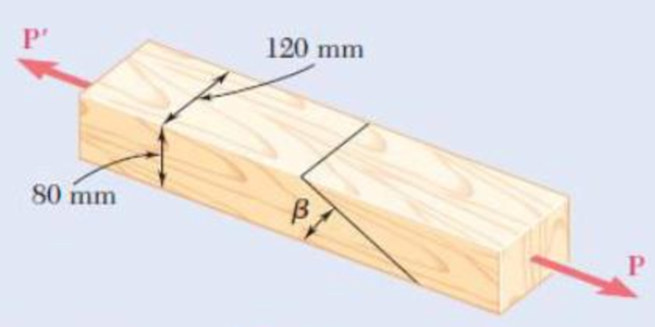
Fig. P7.19 and P7.20
Expert Solution & Answer
Want to see the full answer?
Check out a sample textbook solution
Students have asked these similar questions
Show all work as much as you can and box out answers
Show as much work as possible and box out answers please
on-the-job conditions.
9 ±0.2-
0.5
M
Application questions 1-7 refer to the drawing above.
1. What does the flatness tolerance labeled "G" apply to?
Surface F
A.
B.
Surfaces E and F
C. Surfaces D, E, H, and I
D.
The derived median plane of 12 +0.2
0.5
0.5
CF) 20 ±0.2
0.1
7.
O
12 ±0.2-
H
0.3
ASME Y14.5-2009
Chapter 7 Solutions
EBK MECHANICS OF MATERIALS
Ch. 7.1 - 7.1 through 7.4 For the given state of stress,...Ch. 7.1 - 7.1 through 7.4 For the given state of stress,...Ch. 7.1 - 7.1 through 7.4 For the given state of stress,...Ch. 7.1 - 7.1 through 7.4 For the given state of stress,...Ch. 7.1 - 7.5 through 7.8 For the given state of stress,...Ch. 7.1 - 7.5 through 7.8 For the given state of stress,...Ch. 7.1 - 7.5 through 7.8 For the given state of stress,...Ch. 7.1 - 7.5 through 7.8 For the given state of stress,...Ch. 7.1 - 7.9 through 7.12 For the given state of stress,...Ch. 7.1 - 7.9 through 7.12 For the given state of stress,...
Ch. 7.1 - 7.9 through 7.12 For the given state of stress,...Ch. 7.1 - 7.9 through 7.12 For the given state of stress,...Ch. 7.1 - 7.13 through 7.16 For the given state of stress,...Ch. 7.1 - 7.13 through 7.16 For the given state of stress,...Ch. 7.1 - 7.13 through 7.16 For the given state of stress,...Ch. 7.1 - 7.13 through 7.16 For the given state of stress,...Ch. 7.1 - 7.17 and 7.18 The grain of a wooden member forms...Ch. 7.1 - 7.17 and 7.18 The grain of a wooden member forms...Ch. 7.1 - Two wooden members of 80 120-mm uniform...Ch. 7.1 - Two wooden members of 80 120-mm uniform...Ch. 7.1 - The centric force P is applied to a short post as...Ch. 7.1 - Two members of uniform cross section 50 80 mm are...Ch. 7.1 - The axle of an automobile is acted upon by the...Ch. 7.1 - A 400-lb vertical force is applied at D to a gear...Ch. 7.1 - A mechanic uses a crowfoot wrench to loosen a bolt...Ch. 7.1 - The steel pipe AB has a 102-mm outer diameter and...Ch. 7.1 - For the state of plane stress shown, determine the...Ch. 7.1 - For the state of plane stress shown, determine (a)...Ch. 7.1 - For the state of plane stress shown, determine (a)...Ch. 7.1 - Determine the range of values of x for which the...Ch. 7.2 - Solve Probs. 7.5 and 7.9, using Mohr's circle. 7.5...Ch. 7.2 - Solve Probs. 7.7 and 7.11, using Mohrs circle. 7.5...Ch. 7.2 - Solve Prob. 7.10, using Mohrs circle. 7.9 through...Ch. 7.2 - Solve Prob. 7.12, using Mohr's circle. 7.9 through...Ch. 7.2 - Solve Prob. 7.13, using Mohr's circle. 7.13...Ch. 7.2 - Solve Prob. 7.14, using Mohr's circle. 7.13...Ch. 7.2 - Solve Prob. 7.15, using Mohr's circle. 7.13...Ch. 7.2 - Solve Prob. 7.16, using Mohr's circle. 7.13...Ch. 7.2 - Solve Prob. 7.17, using Mohr's circle. 7.17 and...Ch. 7.2 - Solve Prob. 7.18, using Mohr's circle. 7.17 and...Ch. 7.2 - Solve Prob. 7.19, using Mohr's circle. 7.19 Two...Ch. 7.2 - Solve Prob. 7.20, using Mohr's circle. 7.20 Two...Ch. 7.2 - Solve Prob. 7.21, using Mohrs circle. 7.21 The...Ch. 7.2 - Solve Prob. 7.22, using Mohrs circle. 7.22 Two...Ch. 7.2 - Solve Prob. 7.23, using Mohr's circle. 7.23 The...Ch. 7.2 - Solve Prob. 7.24, using Mohr's circle 7.24 A...Ch. 7.2 - Solve Prob. 7.25, using Mohrs circle. 7.25 A...Ch. 7.2 - Solve Prob. 7.26, using Mohrs circle. 7.26 The...Ch. 7.2 - Solve Prob. 7.27, using Mohr's circle. 7.27 For...Ch. 7.2 - Solve Prob. 7.28, using Mohrs circle. 7.28 For the...Ch. 7.2 - Solve Prob. 7.29, using Mohr's circle. 7.29 For...Ch. 7.2 - Solve Prob. 7.30, using Mohrs circle. 7.30...Ch. 7.2 - Solve Prob. 7.29, using Mohr's circle and assuming...Ch. 7.2 - 7.54 and 7.55 Determine the principal planes and...Ch. 7.2 - 7.54 and 7.55 Determine the principal planes and...Ch. 7.2 - 7.56 and 7.57 Determine the principal planes and...Ch. 7.2 - 7.56 and 7.57 Determine the principal planes and...Ch. 7.2 - For the element shown, determine the range of...Ch. 7.2 - For the element shown, determine the range of...Ch. 7.2 - For the state of stress shown, determine the range...Ch. 7.2 - For the state of stress shown, determine the range...Ch. 7.2 - For the state of stress shown, determine the range...Ch. 7.2 - For the state of stress shown, it is known that...Ch. 7.2 - The Mohr's circle shown corresponds to the state...Ch. 7.2 - (a) Prove that the expression xy 2xywhere x,...Ch. 7.5 - For the state of plane stress shown, determine the...Ch. 7.5 - For the state of plane stress shown, determine the...Ch. 7.5 - For the state of stress shown, determine the...Ch. 7.5 - For the state of stress shown, determine the...Ch. 7.5 - 7.70 and 7.71 For the state of stress shown,...Ch. 7.5 - 7.70 and 7.71 For the state of stress shown,...Ch. 7.5 - 7.72 and 7.73 For the state of stress shown,...Ch. 7.5 - 7.72 and 7.73 For the state of stress shown,...Ch. 7.5 - For the state of stress shown, determine the value...Ch. 7.5 - For the state of stress shown, determine the value...Ch. 7.5 - Prob. 76PCh. 7.5 - For the state of stress shown, determine two...Ch. 7.5 - For the state of stress shown, determine the range...Ch. 7.5 - Prob. 79PCh. 7.5 - Prob. 80PCh. 7.5 - The state of plane stress shown occurs in a...Ch. 7.5 - Prob. 82PCh. 7.5 - The state of plane stress shown occurs in a...Ch. 7.5 - Solve Prob. 7.83, using the...Ch. 7.5 - The 38-mm-diameter shaft AB is made of a grade of...Ch. 7.5 - Solve Prob. 7.85, using the...Ch. 7.5 - The 1.5-in.-diameter shaft AB is made of a grade...Ch. 7.5 - Prob. 88PCh. 7.5 - Prob. 89PCh. 7.5 - Prob. 90PCh. 7.5 - Prob. 91PCh. 7.5 - Prob. 92PCh. 7.5 - Prob. 93PCh. 7.5 - Prob. 94PCh. 7.5 - Prob. 95PCh. 7.5 - Prob. 96PCh. 7.5 - Prob. 97PCh. 7.6 - A spherical pressure vessel has an outer diameter...Ch. 7.6 - A spherical gas container having an inner diameter...Ch. 7.6 - The maximum gage pressure is known to be 1150 psi...Ch. 7.6 - Prob. 101PCh. 7.6 - Prob. 102PCh. 7.6 - A basketball has a 300-mm outer diameter and a...Ch. 7.6 - The unpressurized cylindrical storage tank shown...Ch. 7.6 - Prob. 105PCh. 7.6 - Prob. 106PCh. 7.6 - Prob. 107PCh. 7.6 - Prob. 108PCh. 7.6 - Prob. 109PCh. 7.6 - Prob. 110PCh. 7.6 - Prob. 111PCh. 7.6 - The cylindrical portion of the compressed-air tank...Ch. 7.6 - Prob. 113PCh. 7.6 - Prob. 114PCh. 7.6 - Prob. 115PCh. 7.6 - Square plates, each of 0.5-in. thickness, can be...Ch. 7.6 - The pressure tank shown has a 0.375-in. wall...Ch. 7.6 - Prob. 118PCh. 7.6 - Prob. 119PCh. 7.6 - A pressure vessel of 10-in. inner diameter and...Ch. 7.6 - Prob. 121PCh. 7.6 - A torque of magnitude T = 12 kN-m is applied to...Ch. 7.6 - The tank shown has a 180-mm inner diameter and a...Ch. 7.6 - The compressed-air tank AB has a 250-rnm outside...Ch. 7.6 - In Prob. 7.124, determine the maximum normal...Ch. 7.6 - Prob. 126PCh. 7.6 - Prob. 127PCh. 7.9 - 7.128 through 7.131 For the given state of plane...Ch. 7.9 - 7.128 through 7.131 For the given state of plane...Ch. 7.9 - Prob. 130PCh. 7.9 - 7.128 through 7.131 For the given state of plane...Ch. 7.9 - Prob. 132PCh. 7.9 - Prob. 133PCh. 7.9 - Prob. 134PCh. 7.9 - 7.128 through 7.131 For the given state of plane...Ch. 7.9 - 7.136 through 7.139 The following state of strain...Ch. 7.9 - Prob. 137PCh. 7.9 - Prob. 138PCh. 7.9 - Prob. 139PCh. 7.9 - Prob. 140PCh. 7.9 - 7.140 through 7.143 For the given state of plane...Ch. 7.9 - Prob. 142PCh. 7.9 - Prob. 143PCh. 7.9 - Prob. 144PCh. 7.9 - The strains determined by the use of the rosette...Ch. 7.9 - Prob. 146PCh. 7.9 - Prob. 147PCh. 7.9 - Show that the sum of the three strain measurements...Ch. 7.9 - Prob. 149PCh. 7.9 - Prob. 150PCh. 7.9 - Solve Prob. 7.150, assuming that the rosette at...Ch. 7.9 - Prob. 152PCh. 7.9 - Prob. 153PCh. 7.9 - Prob. 154PCh. 7.9 - Prob. 155PCh. 7.9 - The given state of plane stress is known to exist...Ch. 7.9 - The following state of strain has been determined...Ch. 7 - A steel pipe of 12-in. outer diameter is...Ch. 7 - Two steel plates of uniform cross section 10 80...Ch. 7 - Prob. 160RPCh. 7 - Prob. 161RPCh. 7 - For the state of stress shown, determine the...Ch. 7 - For the state of stress shown, determine the value...Ch. 7 - The state of plane stress shown occurs in a...Ch. 7 - The compressed-air tank AB has an inner diameter...Ch. 7 - For the compressed-air tank and loading of Prob....Ch. 7 - Prob. 167RPCh. 7 - Prob. 168RPCh. 7 - Prob. 169RP
Knowledge Booster


Learn more about
Need a deep-dive on the concept behind this application? Look no further. Learn more about this topic, mechanical-engineering and related others by exploring similar questions and additional content below.Similar questions
- elements, each with a length of 1 m. Determine the temperature on node 1, 2, 3, 4. 3. Solve the strong form analytically (you may choose Maple, MATLAB or Mathematica to help you solve this ODE). Compare the FE approximate temperature distribution through the block against the analytical solution. 1 (1) 200 °C 2 (2) 3 m 3 (3)arrow_forwardCompute the horizontal and vertical components of the reaction at the pin A. B A 30° 0.75 m 1 m 60 N 0.5 m 90 N-marrow_forwardA particle is held and then let go at the edge of a circular shaped hill of radius R = shown below. The angular motion of the particle is governed by the following ODE: + 0.4 02 - 2 cos 0 + 0.8 sin 0 = 0 where is the angle in rad measured from the top (CCW: +), ė 5m, as = wis the velocity in rad/s, ==a is the angular acceleration in rad/s². Use MATLAB to numerically integrate the second order ODE and predict the motion of the particle. (a) Plot and w vs. time (b) How long does it take for the particle to fall off the ring at the bottom? (c) What is the particle speed at the bottom. Hint v = Rw. in de all questions the particles inside the tube. /2/07/25 Particle R 0 0 R eled witharrow_forward
- If FA = 40 KN and FB = 35 kN, determine the magnitude of the resultant force and specify the location of its point of application (x, y) on the slab. 30 kN 0.75 m 90 kN FB 2.5 m 20 kN 2.5 m 0.75 m FA 0.75 m 3 m 3 m 0.75 marrow_forwardThe elastic bar from Problem 1 spins with angular velocity ω about an axis, as shown in the figure below. The radial acceleration at a generic point x along the bar is a(x) = ω 2 x. Under this radial acceleration, the bar stretches along x with displacement function u(x). The displacement u(x) is governed by the following equations: ( d dx (σ(x)) + ρa(x) = 0 PDE σ(x) = E du dx Hooke’s law (2) where σ(x) is the axial stress in the rod, ρ is the mass density, and E is the (constant) Young’s modulus. The bar is pinned on the rotation axis at x = 0 and it is also pinned at x = L. Determine:1. Appropriate BCs for this physical problem.2. The displacement function u(x).3. The stress function σ(x).arrow_forwardThe heated rod from Problem 3 is subject to a volumetric heatingh(x) = h0xLin units of [Wm−3], as shown in the figure below. Under theheat supply the temperature of the rod changes along x with thetemperature function T(x). The temperature T(x) is governed by thefollowing equations:(−ddx (q(x)) + h(x) = 0 PDEq(x) = −kdTdx Fourier’s law of heat conduction(4)where q(x) is the heat flux through the rod and k is the (constant)thermal conductivity. Both ends of the bar are in contact with a heatreservoir at zero temperature. Determine:1. Appropriate BCs for this physical problem.2. The temperature function T(x).3. The heat flux function q(x).arrow_forward
- A heated rod of length L is subject to a volumetric heating h(x) = h0xLinunits of [Wm−3], as shown in the figure below. Under the heat supply thetemperature of the rod changes along x with the temperature functionT(x). The temperature T(x) is governed by the following equations:(−ddx (q(x)) + h(x) = 0 PDEq(x) = −kdTdx Fourier’s law of heat conduction(3)where q(x) is the heat flux through the rod and k is the (constant)thermal conductivity. The left end of the bar is in contact with a heatreservoir at zero temperature, while the right end of the bar is thermallyinsulated. Determine:1. Appropriate BCs for this physical problem.2. The temperature function T(x).3. The heat flux function q(x).arrow_forwardCalculate the mean piston speed (in mph) for a Formula 1 engine running at 14,750 rpm with a bore of 80mm and a stroke of 53mm. Estimate the average acceleration imparted on the piston as it moves from TDC to 90 degrees ATDCarrow_forwardCalculate the compression ratio of an engine with a stroke of 4.2inches a bore of 4.5 inches and a clearance volume of 6.15 cubic inches. Discuss whether or not this is a realistic compression ratio for a street engine and what octane rating of fuel it would need to run correctlyarrow_forward
- Draw the free-body diagram for the pinned assembly shown. Find the magnitude of the forces acting on each member of the assembly. 1500 N 1500 N C 45° 45° 45° 45° 1000 mmarrow_forwardAn elastic bar of length L spins with angular velocity ω about an axis, as shown in the figure below. The radial acceleration at a generic point x along the bar is a(x) = ω 2 x. Due to this radial acceleration, the bar stretches along x with displacement function u(x). The displacement u(x) is governed by the following equations: ( d dx (σ(x)) + ρa(x) = 0 PDE σ(x) = E du dx Hooke’s law (1) where σ(x) is the axial stress in the rod, ρ is the mass density, and E is the (constant) Young’s modulus. The bar is pinned on the rotation axis at x = 0, and it is free at x = L. Determine:1. Appropriate BCs for this physical problem.2. The displacement function u(x).3. The stress function σ(x).arrow_forwardWith reference to the given figure: a) Draw a free-body diagram of the structure supporting the pulley. b) Draw shear and bending moment diagrams for both the vertical and horizontal portions of the structure. 48 in. 100 lb 12 in. Cable 27 in. 12-in. pulley radius 100 lb Cablearrow_forward
arrow_back_ios
SEE MORE QUESTIONS
arrow_forward_ios
Recommended textbooks for you
 Elements Of ElectromagneticsMechanical EngineeringISBN:9780190698614Author:Sadiku, Matthew N. O.Publisher:Oxford University Press
 Mechanics of Materials (10th Edition)Mechanical EngineeringISBN:9780134319650Author:Russell C. HibbelerPublisher:PEARSON
 Thermodynamics: An Engineering ApproachMechanical EngineeringISBN:9781259822674Author:Yunus A. Cengel Dr., Michael A. BolesPublisher:McGraw-Hill Education
 Control Systems EngineeringMechanical EngineeringISBN:9781118170519Author:Norman S. NisePublisher:WILEY
 Mechanics of Materials (MindTap Course List)Mechanical EngineeringISBN:9781337093347Author:Barry J. Goodno, James M. GerePublisher:Cengage Learning
 Engineering Mechanics: StaticsMechanical EngineeringISBN:9781118807330Author:James L. Meriam, L. G. Kraige, J. N. BoltonPublisher:WILEY
Elements Of Electromagnetics
Mechanical Engineering
ISBN:9780190698614
Author:Sadiku, Matthew N. O.
Publisher:Oxford University Press
Mechanics of Materials (10th Edition)
Mechanical Engineering
ISBN:9780134319650
Author:Russell C. Hibbeler
Publisher:PEARSON
Thermodynamics: An Engineering Approach
Mechanical Engineering
ISBN:9781259822674
Author:Yunus A. Cengel Dr., Michael A. Boles
Publisher:McGraw-Hill Education
Control Systems Engineering
Mechanical Engineering
ISBN:9781118170519
Author:Norman S. Nise
Publisher:WILEY
Mechanics of Materials (MindTap Course List)
Mechanical Engineering
ISBN:9781337093347
Author:Barry J. Goodno, James M. Gere
Publisher:Cengage Learning
Engineering Mechanics: Statics
Mechanical Engineering
ISBN:9781118807330
Author:James L. Meriam, L. G. Kraige, J. N. Bolton
Publisher:WILEY
BEARINGS BASICS and Bearing Life for Mechanical Design in 10 Minutes!; Author: Less Boring Lectures;https://www.youtube.com/watch?v=aU4CVZo3wgk;License: Standard Youtube License