
Concept explainers
Videos
A steel pipe of 12-in. outer diameter is fabricated from
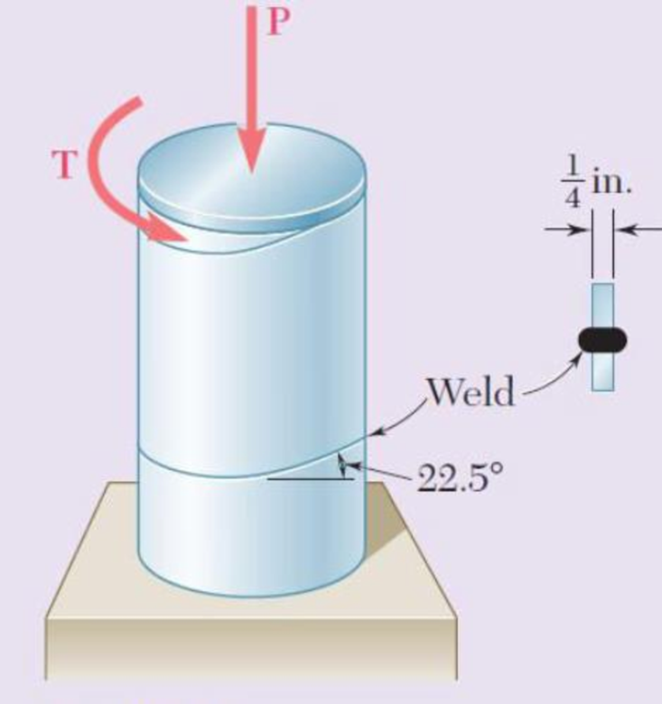
Fig. P7.158
Fund the normal and in-plane shearing stresses, normal and tangential stress to the weld.
Answer to Problem 158RP
The normal stress in x-axis is
The normal stress in y-axis is
The shearing stress in xy-plane is
The normal stress in the weld is
The tangential stress in the weld is
Explanation of Solution
Given information:
The outer diameter of the steel pipe is
The thickness of the plate is
The plate makes an angle with plane perpendicular to the pipe is
The magnitude of the axial force P is 40 kips.
The torque applied in the pipe T is 80 kip-in.
Calculation:
Find the inner diameter of the steel
Substitute 12 in. for
Find the area of the steel pipe (A) using the equation.
Substitute 12 in. for
Find the polar moment of inertia (J) of the steel pipe using the equation.
Substitute 12 in. for
Find the normal stress
Substitute 40 kips for P and
The normal stress in x-axis is
The normal stress in y-axis is
Find the shearing stress
Substitute 80 kip-in. for T, 12 in. for
The shearing stress in xy-plane is
Show the stress element for pipe as in Figure 1.
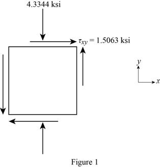
Therefore,
The normal stress in x-axis is
The normal stress in y-axis is
The shearing stress in xy-plane is
Consider the axes
The normal stress in weld is
The shearing stress in weld is
Find the normal stress in the weld using the equation.
Substitute 0 for
Find the tangential stress in the weld using the equation.
Substitute 0 for
Show the stress element for weld as in Figure 2.
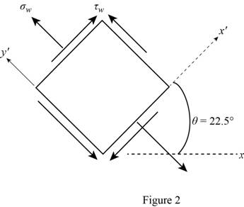
Therefore,
The normal stress in the weld is
The tangential stress in the weld is
Want to see more full solutions like this?
Chapter 7 Solutions
EBK MECHANICS OF MATERIALS


- 1. 1.25 m³ of saturated liquid water at 225°C is expanded isothermally in a closed system until its quality is 75 percent. Determine the total work produced by this expansion, in kJ.arrow_forwardAn undamped single-degree-of-freedom system is subjected to dynamic excitation as shown in Figure 1.• System properties: m = 1, c = 0, k = (6π)2.• Force excitation: p(t) = posin(ωt) where po = 9 and ω = 2π.• Initial conditions: u(t = 0) = 0 and ̇u(t = 0) = 0.Please, complete Parts (a) through (d) using any computational tool of your preference. The preferred toolis MATLAB. Print and turn in a single pdf file that will include your code/calculations and your plots.(a) Generate the solution using a linear interpolation of the load over each time step (note that hereyou can use the undamped coefficients). Plot the displacement response for the first 4 seconds andcompare to the exact closed form solution. Repeat using the following time step sizes, ∆t = 0.01,0.05, 0.15, 0.20 seconds. Include the closed form solution and the solutions for different ∆t values in asingle plot. Please, provide your observations by comparing the closed form solution with the solutionsderived using the four…arrow_forwardAssume multiple single degree of freedom systems with natural periods T ∈ [0.05, 2.00] seconds with in-crement of period dT = 0.05 seconds. Assume three cases of damping ratio: Case (A) ξ = 0%; Case (B)ξ = 2%; Case (C) ξ = 5%. The systems are initially at rest. Thus, the initial conditions are u(t = 0) = 0 anḋu(t = 0) = 0. The systems are subjected to the base acceleration that was provided in the ElCentro.txt file(i.e., first column). For the systems in Case (A), Case (B), and Case (C) and for each natural period computethe peak acceleration, peak velocity, and peak displacement responses to the given base excitation. Please,use the Newmark method for β = 1/4 (average acceleration) to compute the responses. Create threeplots with three lines in each plot. The first plot will have the peak accelerations in y-axis and the naturalperiod of the system in x-axis. The second plot will have the peak velocities in y-axis and the natural periodof the system in x-axis. The third plot will have…arrow_forward
- Both portions of the rod ABC are made of an aluminum for which E = 70 GPa. Based on the given information find: 1- deformation at A 2- stress in BC 3- Total strain 4- If v (Poisson ratio is 0.25, find the lateral deformation of AB Last 3 student ID+ 300 mm=L2 724 A P=Last 2 student ID+ 300 KN 24 24 Diameter Last 2 student ID+ 15 mm Last 3 student ID+ 500 mm=L1 724 C B 24 Q=Last 2 student ID+ 100 KN 24 Diameter Last 2 student ID+ 40 mmarrow_forwardQ2Two wooden members of uniform cross section are joined by the simple scarf splice shown. Knowing that the maximum allowable tensile stress in the glued splice is 75 psi, determine (a) the largest load P that can be safely supported, (b) the corresponding shearing stress in the splice. น Last 1 student ID+5 inch=W =9 4 L=Last 1 student ID+8 inch =12 60° P'arrow_forwardQ4 The two solid shafts are connected by gears as shown and are made of a steel for which the allowable shearing stress is 7000 psi. Knowing the diameters of the two shafts are, respectively, dBC determine the largest torque Tc that can be applied at C. 4 and dEF dBC=Last 1 student ID+3 inch dEF=Last 1 student ID+1 inch 7 R=Last 1 Student ID+5 inch 9 R B Tc 2.5 in. E TF Harrow_forward
- Experiment تكنولوجيا السيارات - Internal Forced convenction Heat transfer Air Flow through Rectangular Duct. objective: Study the convection heat transfer of air flow through rectangular duct. Valve Th Top Dead Centre Exhaust Valve Class CP. N; ~ RIVavg Ti K 2.11 Te To 18.8 21.3 45.8 Nath Ne Pre Calculations:. Q = m cp (Te-Ti) m: Varg Ac Acca*b Q=hexp As (Ts-Tm) 2 2.61 18.5 20.846.3 Tm = Te-Ti = 25 AS-PL = (a+b)*2*L Nu exp= Re-Vavy D heep Dh k 2ab a+b Nu Dh the- (TS-Tm) Ts. Tmy Name / Nu exp Naxe بب ارتدان العشريarrow_forwardProcedure:1- Cartesian system, 2D3D,type of support2- Free body diagram3 - Find the support reactions4- If you find a negativenumber then flip the force5- Find the internal force3D∑Fx=0∑Fy=0∑Fz=0∑Mx=0∑My=0\Sigma Mz=02D\Sigma Fx=0\Sigma Fy=0\Sigma Mz=05- Use method of sectionand cut the elementwhere you want to findarrow_forwardProcedure:1- Cartesian system, 2D3D,type of support2- Free body diagram3 - Find the support reactions4- If you find a negativenumber then flip the force5- Find the internal force3D∑Fx=0∑Fy=0∑Fz=0∑Mx=0∑My=0\Sigma Mz=02D\Sigma Fx=0\Sigma Fy=0\Sigma Mz=05- Use method of sectionand cut the elementwhere you want to findthe internal force andkeep either side of thearrow_forward
- Procedure: 1- Cartesian system, 2D3D, type of support 2- Free body diagram 3 - Find the support reactions 4- If you find a negative number then flip the force 5- Find the internal force 3D ∑Fx=0 ∑Fy=0 ∑Fz=0 ∑Mx=0 ∑My=0 ΣMz=0 2D ΣFx=0 ΣFy=0 ΣMz=0 5- Use method of section and cut the element where you want to find the internal force and keep either side of thearrow_forwardProcedure:1- Cartesian system, 2D3D,type of support2- Free body diagram3 - Find the support reactions4- If you find a negativenumber then flip the force5- Find the internal force3D∑Fx=0∑Fy=0∑Fz=0∑Mx=0∑My=0\Sigma Mz=02D\Sigma Fx=0\Sigma Fy=0\Sigma Mz=05- Use method of sectionand cut the elementwhere you want to findthe internal force andkeep either side of thearrow_forwardProcedure: 1- Cartesian system, 2(D)/(3)D, type of support 2- Free body diagram 3 - Find the support reactions 4- If you find a negative number then flip the force 5- Find the internal force 3D \sum Fx=0 \sum Fy=0 \sum Fz=0 \sum Mx=0 \sum My=0 \Sigma Mz=0 2D \Sigma Fx=0 \Sigma Fy=0 \Sigma Mz=0 5- Use method of section and cut the element where you want to find the internal force and keep either side of the sectionarrow_forward
 Elements Of ElectromagneticsMechanical EngineeringISBN:9780190698614Author:Sadiku, Matthew N. O.Publisher:Oxford University Press
 Mechanics of Materials (10th Edition)Mechanical EngineeringISBN:9780134319650Author:Russell C. HibbelerPublisher:PEARSON
 Thermodynamics: An Engineering ApproachMechanical EngineeringISBN:9781259822674Author:Yunus A. Cengel Dr., Michael A. BolesPublisher:McGraw-Hill Education
 Control Systems EngineeringMechanical EngineeringISBN:9781118170519Author:Norman S. NisePublisher:WILEY
 Mechanics of Materials (MindTap Course List)Mechanical EngineeringISBN:9781337093347Author:Barry J. Goodno, James M. GerePublisher:Cengage Learning
 Engineering Mechanics: StaticsMechanical EngineeringISBN:9781118807330Author:James L. Meriam, L. G. Kraige, J. N. BoltonPublisher:WILEY