
Concept explainers
Videos
For the state of stress shown, determine two values of σy for which the maximum shearing stress is 10 ksi.
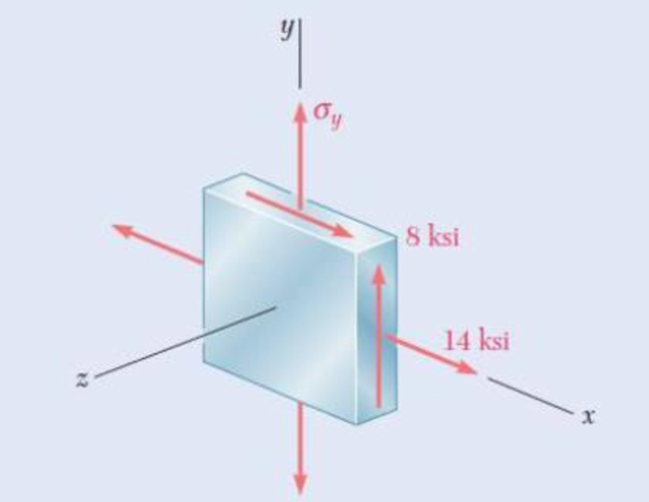
Fig. P7.77
The two values of
Answer to Problem 77P
The values of
Explanation of Solution
Given information:
The components of stress
The maximum shear stress
Calculation:
Consider
Modify Equation (1) as shown below.
Calculate the average normal stress
Substitute
Calculate the value u as shown below.
Substitute
Case 1:
For
Calculate the value of
Substitute
Calculate the average normal stress
Substitute
Calculate the principal stresses
Substitute
Hence, the principal stresses are
Calculate the maximum shearing stress as shown below.
Substitute
For
Calculate the value of
Substitute
Calculate the average normal stress
Substitute
Calculate the principal stresses
Substitute
Hence, the principal stresses are
Calculate the maximum shearing stress as shown below.
Substitute
Hence, the value of
Case 2:
Assume the minimum principal stress
Calculate the maximum principal stress as shown below.
Substitute
The maximum principal stress
Substitute
Substitute
Calculate the value of
Substitute
Calculate the value of R as shown below.
Substitute
Calculate the average normal stress
Substitute
Calculate the principal stress
Substitute
Hence, the principal stresses
Therefore, the value of
Want to see more full solutions like this?
Chapter 7 Solutions
EBK MECHANICS OF MATERIALS


- Solve this problem and show all of the workarrow_forwardSolve this problem and show all of the workarrow_forwarddraw the pneumatic circuit to operate a double-acting cylinder with: 1. Extension: Any of two manual conditions plus cylinder fully retracted, → Extension has both meter-in and meter-out, 2. Retraction: one manual conditions plus cylinder fully extended, → Retraction is very fast using quick exhaust valve.arrow_forward
- Correct answer is written below. Detailed and complete solution with fbd only. I will upvote, thank you. Expert solution plsarrow_forwardCorrect answer is written below. Detailed and complete solution with fbd only. I will upvote, thank you.arrow_forwardCorrect answer is written below. Detailed and complete solution with fbd only. I will upvote, thank you.arrow_forward
- Correct answer is written below. Detailed and complete solution only with fbd. I will upvote, thank you.arrow_forwardCorrect answer is written below. Detailed and complete solution only. I will upvote, thank you.arrow_forwardCorrect answer is written below. Detailed and complete solution with fbd only. I will upvote, thank you.arrow_forward
- Correct answer is written below. Detailed and complete solution only. I will upvote, thank you.arrow_forwardCorrect answer is written below. Detailed and complete solution with fbd only. I will upvote, thank you.arrow_forwardCorrect answer is written below. Detailed and complete solution only. I will upvote, thank you.arrow_forward
 Elements Of ElectromagneticsMechanical EngineeringISBN:9780190698614Author:Sadiku, Matthew N. O.Publisher:Oxford University Press
 Mechanics of Materials (10th Edition)Mechanical EngineeringISBN:9780134319650Author:Russell C. HibbelerPublisher:PEARSON
 Thermodynamics: An Engineering ApproachMechanical EngineeringISBN:9781259822674Author:Yunus A. Cengel Dr., Michael A. BolesPublisher:McGraw-Hill Education
 Control Systems EngineeringMechanical EngineeringISBN:9781118170519Author:Norman S. NisePublisher:WILEY
 Mechanics of Materials (MindTap Course List)Mechanical EngineeringISBN:9781337093347Author:Barry J. Goodno, James M. GerePublisher:Cengage Learning
 Engineering Mechanics: StaticsMechanical EngineeringISBN:9781118807330Author:James L. Meriam, L. G. Kraige, J. N. BoltonPublisher:WILEY