
Videos
(a)
The six appropriate boundary conditions on both velocity and pressure.
Answer to Problem 136P
The first boundary condition is
The second boundary condition is
The third boundary condition is
The fourth boundary condition is
The fifth boundary condition is
The sixth boundary condition
is
Explanation of Solution
Given information:
The following figure shows that two parallel flat plates.
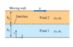
Figure-( 1)
Assume, at the point of wall and fluid, the velocity of the fluid is equal to zero.
Write the expression for velocity of the fluid 1,
Here, the velocity of fluid 1 is
Assume, the velocity of the fluid 2 at the free surface of the wall is equal to the velocity of the moving plates.
Write the expressions for the velocity of fluid 2.
Here, the velocity of fluid 2 is
Write the expression for velocity at interface.
Write the expression for rate of shear stress.
Here, the kinematic coefficient of fluid is
Write the expression for the shear stress acting on fluid 1.
Here, the kinematic coefficient of fluid 1 is
Write the expression for the shear stress acting on fluid 2.
Here, the kinematic coefficient of fluid 2 is
Write the expression for the rate of shear stress at interface.
Write the expression for pressure at the bottom of the flow,
Here, the pressure is
Write the expression for the pressure at the interface of fluid 1.
Here, the pressure at the fluid 1 is
Write the expression for the pressure at the interface of fluid 2.
Here, the pressure at the fluid 1 is
Assume, at the interface of the fluid the pressure cannot have discontinuity and the surface is ignored.
Write the expression for the pressure at interface of fluid.
Conclusion:
The first boundary condition is
The second boundary condition is
The third boundary condition is
The fourth boundary conditions is
The fifth boundary condition is
The sixth boundary condition
is
(b)
The expressions for the velocity of fluid 1 and 2.
Answer to Problem 136P
The expression for the velocity of fluid 1 is
The expression for the velocity of fluid 2 is
Explanation of Solution
Write the expression for
Here, the velocity of flow for fluid 1 is
Write the expression for
Here, the velocity of flow for fluid 2 is
Calculation:
Integrate Equation (XIII) with respect to
Here, the constant is
Integrate Equation (XIII) with respect to
Here, the constant is
Integrate Equation (XIV) with respect to
Here, the constant is
Integrate Equation (XIV) with respect to
Here, the constant is
Substitute
Substitute
Substitute
Substitute
Substitute
Differentiate Equation (XXI) with respect to
Substitute
Substitute
Substitute
Substitute
Conclusion:
The expression for the velocity of fluid 1 is
The expression for the velocity of fluid 2 is
(c)
The expressions for pressure of fluid 1 and 2.
Answer to Problem 136P
The expression for the pressure of fluid 1 is
The expression for the pressure of fluid 2 is
Explanation of Solution
Write the expression for
Here, the density of the fluid 1 is
Write the expression for
Here, the density of the fluid 2 is
Calculation:
Integrate Equation (XXV) with respect to
Here, the constant is
Substitute
Substitute
Integrate Equation (XXVI) with respect to
Here, the constant is
Substitute
Substitute
Substitute
Conclusion:
The expression for the pressure of fluid 1 is
The expression for the pressure of fluid 2 is
(d)
The plot
Answer to Problem 136P
The following Figure-(2) represents the velocities of fluid 1 and 2.

Explanation of Solution
Given information:
The fluid 1 be water and the fluid 2 be unused engine oil, at
The following figure shows that two parallel flat plates.
Write the expression for the velocity of fluid 1.
Here, the distance is
Write the expression for the velocity of fluid 2.
Calculation:
Refer the Table-A-3E, "Properties of saturated water", to obtain the value of dynamic viscosity of water is
Refer the Table-A-7E, "Properties of the atmosphere at high attitude", to obtain the value of dynamic viscosity of unused engine oil is
Substitute
Substitute
The following graph represents the velocities of fluid 1 and 2.
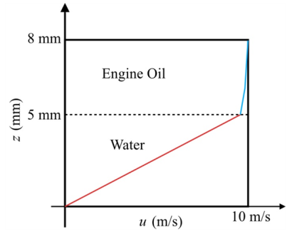
Figure-(2)
In the fluid 1 the linear curve is increasing with respect to the velocity of flow and height of fluid 1. In the fluid 2 the curve is increasing with respect to the velocity of flow and height of fluid 2.
Conclusion:
The following Figure-(2) represents the velocities of fluid 1 and 2.

Want to see more full solutions like this?
Chapter 7 Solutions
Fluid Mechanics: Fundamentals and Applications


- Liquid water enters the boiler at 60 bar. Steam exits the boiler at 60 bar, 540°C and undergoes a throttling process to 40 bar before entering the turbine. Steam expands adiabatically through the turbine to 5 bar, 240°C, and then undergoes a throttling process to 1 bar before entering the condenser. Kinetic and potential energy effects can be ignored. Draw a Temperature-Entropy diagram and mark each of the states 2-5 on this diagram. Determine the power generated by the turbine, in kJ per kg of steam flowing. For the valves and the turbine, evaluate the rate of entropy production, each in kJ/K per kg of steam flowing.arrow_forwardFind the componenets of reactions at pins of A, B and D please show the detailed process and instructions for learning draw out all diagrams please and thank youarrow_forwardA cast iron cylinder of 200 mm inner diameter and 12.5 mm thick is closely wound with a layer of 4 mm diameter steel wire under a tensile stress of 55 MN/m². Determine the stresses set up in the cylinder and steel wire if water under a pressure of 3 MN/m² is admitted in the cylinder. Take E= 100 GN/m², E = 200 GN/m² and Poisson's ratio = 0.25.arrow_forward
- What is the effect of a clogged fuel injector?arrow_forwardYou are asked to design a unit to condense ammonia. The required condensation rate is 0.09kg/s. Saturated ammonia at 30 o C is passed over a vertical plate (10 cm high and 25 cm wide).The properties of ammonia at the saturation temperature of 30°C are hfg = 1144 ́10^3 J/kg andrho_v = 9.055 kg/m 3 . Use the properties of liquid ammonia at the film temperature of 20°C (Ts =10 o C):Pr = 1.463 rho_l= 610.2 kf/m^3 liquid viscosity= 1.519*10^-4 kg/ ms kinematic viscosity= 2.489*10^-7 m^2/s Cpl= 4745 J/kg C kl=0.4927 W/m C hfg*=hfg+0.68Cpl(Tsat-Given Ts) a) Instead of one plate you want to use small plates and install many of them. Calculate the requiredsurface temperature to achieve the desired condensation rate (0.09 kg/s) if you install 36vertical plates (with the same dimension as above: 10 cm high and 25 cm wide).arrow_forward11-19 designed in Problem The shaft shown in figure P11-4 was 10-19, for the data in the row(s) assigned from table PII-1, and the corresponding diameter of shaft found in Problem 10-19, design suitable bearings 5 E8 cycles at the load for at least State all assumptions. to support 1200rpm. (a) Using hydrodynamically lubricated bronze sleeve bearings with ON = 40, Lld = 0.8, and clearance ratio 0.0025. of a ← gear T gear Key figure PI-4 Given from the problem 10-19 we get d= 1.153 in from the table 11-1 we get a = 16 in b= 18in L= 20inarrow_forward
- In an irrigation system, the following characteristics of the pipe network are available.• 100 meters of 4" PVC pipe, 3 gate valves• 500 meters of 3" PVC pipe, 4 gate valves• 200 meters of 2" H.G. pipe, 2 globe valves• 50 litres per second circulate in the pipes:Calculate:1. Total energy losses in meters.2. Leaks in pipes.3. Losses in accessories.4. Calculate the equivalent pipe of that system assuming only pipes without fittings.Solve the problem without artificial intelligence, solve by one of the expertsarrow_forwardIn a series pipe, calculate the diameter 2 according to the following:• Ltotal: 325 m• L1: 52 m, D1: 3/4"• L2: 254 m, D2:?• L3: 19 m, D: 1-1/4".Indicate the nominal diameter. Solve without using artificial inteligence, solve by one of the expertsarrow_forwardWhat is the critical speed of the shaft in rad/s for one, two, and three elements?arrow_forward
- 2. Express the following complex numbers in rectangular form. (a) z₁ = 2еjл/6 (b) Z2=-3e-jπ/4 (c) Z3 = √√√3e-j³/4 (d) z4 = − j³arrow_forwardA prismatic beam is built into a structure. You can consider the boundary conditions at A and B to be fixed supports. The beam was originally designed to withstand a triangular distributed load, however, the loading condition has been revised and can be approximated by a cosine function as shown in the figure below. You have been tasked with analysing the structure. As the beam is prismatic, you can assume that the bending rigidity (El) is constant. wwo cos 2L x A B Figure 3: Built in beam with a varying distributed load In order to do this, you will: a. Solve the reaction forces and moments at point A and B. Hint: you may find it convenient to use the principal of superposition. (2%) b. Plot the shear force and bending moment diagrams and identify the maximum shear force and bending moment. (2%) c. Develop an expression for the vertical deflection. Clearly state your expression in terms of x. (1%)arrow_forwardQuestion 1: Beam Analysis Two beams (ABC and CD) are connected using a pin immediately to the left of Point C. The pin acts as a moment release, i.e. no moments are transferred through this pinned connection. Shear forces can be transferred through the pinned connection. Beam ABC has a pinned support at point A and a roller support at Point C. Beam CD has a roller support at Point D. A concentrated load, P, is applied to the mid span of beam CD, and acts at an angle as shown below. Two concentrated moments, MB and Mc act in the directions shown at Point B and Point C respectively. The magnitude of these moments is PL. Moment Release A B с ° MB = PL Mc= = PL -L/2- -L/2- → P D Figure 1: Two beam arrangement for question 1. To analyse this structure, you will: a) Construct the free body diagrams for the structure shown above. When constructing your FBD's you must make section cuts at point B and C. You can represent the structure as three separate beams. Following this, construct the…arrow_forward
 Principles of Heat Transfer (Activate Learning wi...Mechanical EngineeringISBN:9781305387102Author:Kreith, Frank; Manglik, Raj M.Publisher:Cengage Learning