
Videos
6.119 through 6.121 Each of the frames shown consists of two L-shaped members connected by two rigid links. For each frame, determine the reactions at the supports and indicate whether the frame is rigid.
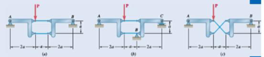
Fig. P6.121
The reactions at the frame and the rigidness of the frame.
Answer to Problem 6.121P
The reactions at the frame for figure (a) is
Explanation of Solution
The following figure gives the free body diagram of the first part of the member in figure P6.121(a).
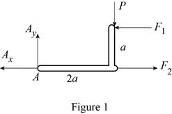
Write the equation to find the moment of force.
Here,
Write the equation to find the total moment about the point
Write the equations for equilibrium for the free body diagram in figure 1.
Here,
The following figure gives the free body diagram of the second part of the member in figure P6.121(a).
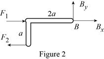
Write the equations for equilibrium for the free body diagram in figure 2.
Here,
The following figure gives the free body diagram of the first part of the member in figure P6.119(b).
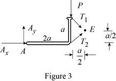
Write the equations for equilibrium for the free body diagram in figure 3.
Here,
The following figure gives the free body diagram of the second part of the member in figure P6.119(b).
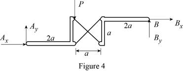
Write the equations for equilibrium for the free body diagram in figure 4.
Here,
The following figure gives the free body diagram of the member in figure P6.119(c).
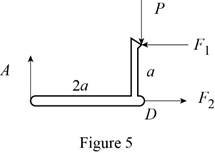
Write the equations for equilibrium for the free body diagram in figure 5.
Here,
The following figure gives the free body diagram of right part of the member in figure P6.119(c).
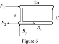
Write the equations for equilibrium for the free body diagram in figure 6.
Here,
Write the expression to find the magnitude of the vector from its components.
Here,
Write the equation to find the angle of orientation of the vector
Conclusion:
Solve equation (I) using figure 1.
Rewrite the above equation.
Solve equation (III) using figure 1.
Rewrite the above equation.
Solve equation (IV) using figure 2.
Rewrite the above equation.
Solve equation (V) using figure 2.
Substitute
Solve equation (VI) using figure 2.
Substitute
Rewrite equation (XIV) in terms of the vector
Substitute
Rewrite equation (XV) in terms of the vector
Substitute
Rewrite equation (XIV) in terms of the vector
Substitute
Solve equation (VII) using figure 3.
Rewrite the above equation.
Solve equation (VIII) using figure 4.
Rewrite the above equation.
Solve the conditions obtained from figure 3 and 4.
Solve equation (IX) using figure 5.
Rewrite the above equation to find
Solve equation (X) using figure 5.
Substitute
Solve equation (XI) using figure 5.
Substitute
Solve equation (XII) using figure 6.
Substitute
Solve equation (XII) to the right using figure 6.
Substitute
Solve equation (XII) upwards using figure 6.
Substitute
Therefore, the reactions at the frame for figure (a) is
Want to see more full solutions like this?
Chapter 6 Solutions
Vector Mechanics for Engineers: Statics


- Solve this probem and show all of the workarrow_forwardThe differential equation of a cruise control system is provided by the following equation: WRITE OUT SOLUTION DO NOT USE A COPIED SOLUTION Find the closed loop transfer function with respect to the reference velocity (vr) . a. Find the poles of the closed loop transfer function for different values of K. How does the poles move as you change K? b. Find the step response for different values of K and plot in MATLAB. What can you observe?arrow_forwardSolve this problem and show all of the workarrow_forward
- Determine the minimum applied force P required to move wedge A to the right. The spring is compressed a distance of 175 mm. Neglect the weight of A and B. The coefficient of static friction for all contacting surface is μs = 0.35. Neglect friction at the rollers. k = = 15 kN/m P A B 10°arrow_forwardDO NOT COPY SOLUTION- will report The differential equation of a cruise control system is provided by the following equation: Find the closed loop transfer function with respect to the reference velocity (vr) . a. Find the poles of the closed loop transfer function for different values of K. How does the poles move as you change K? b. Find the step response for different values of K and plot in MATLAB. What can you observe?arrow_forwarda box shaped barge 37m long, 6.4 m beam, floats at an even keel draught of 2.5 m in water density 1.025 kg/m3. If a mass is added and the vessel moves into water density 1000 kg/m3, determine the magnitude of this mass if the fore end and aft end draughts are 2.4m and 3.8m respectively.arrow_forward
- a ship 125m long and 17.5m beam floats in seawater of 1.025 t/m3 at a draught of 8m. the waterplane coefficient is 0.83, block coefficient 0.759 and midship section area coefficient 0.98. calculate i) prismatic coefficient ii) TPC iii) change in mean draught if the vessel moves into water of 1.016 t/m3arrow_forwardc. For the given transfer function, find tp, ts, tr, Mp . Plot the resulting step response. G(s) = 40/(s^2 + 4s + 40) handplot only, and solve for eacharrow_forwardA ship of 9000 tonne displacement floats in fresh water of 1.000 t/m3 at a draught 50 mm below the sea water line. The waterplane area is 1650 m2. Calculate the mass of cargo which must be added so that when entering seawater of 1.025 t/m3 it floats at the seawater line.arrow_forward
- A ship of 15000 tonne displacement floats at a draught of 7 metres in water of 1.000t/cub. Metre.It is required to load the maximum amount of oil to give the ship a draught of 7.0 metre in seawater ofdensity 1.025 t/cub.metre. If the waterplane area is 2150 square metre, calculate the massof oil requiredarrow_forwardA ship of 8000 tonne displacement floats in seawater of 1.025 t/m3 and has a TPC of 14. The vessel moves into fresh water of 1.000 t/m3 and loads 300 tonne of oil fuel. Calculate the change in mean draught.arrow_forwardAuto Controls DONT COPY ANSWERS - will report Perform the partial fraction expansion of the following transfer function and find the impulse response: G(s) = (s/2 + 5/3) / (s^2 + 4s + 6) G(s) =( 6s^2 + 50) / (s+3)(s^2 +4)arrow_forward
 Elements Of ElectromagneticsMechanical EngineeringISBN:9780190698614Author:Sadiku, Matthew N. O.Publisher:Oxford University Press
 Mechanics of Materials (10th Edition)Mechanical EngineeringISBN:9780134319650Author:Russell C. HibbelerPublisher:PEARSON
 Thermodynamics: An Engineering ApproachMechanical EngineeringISBN:9781259822674Author:Yunus A. Cengel Dr., Michael A. BolesPublisher:McGraw-Hill Education
 Control Systems EngineeringMechanical EngineeringISBN:9781118170519Author:Norman S. NisePublisher:WILEY
 Mechanics of Materials (MindTap Course List)Mechanical EngineeringISBN:9781337093347Author:Barry J. Goodno, James M. GerePublisher:Cengage Learning
 Engineering Mechanics: StaticsMechanical EngineeringISBN:9781118807330Author:James L. Meriam, L. G. Kraige, J. N. BoltonPublisher:WILEY