
Vector Mechanics for Engineers: Statics
12th Edition
ISBN: 9781259977268
Author: Ferdinand P. Beer, E. Russell Johnston Jr., David Mazurek
Publisher: McGraw-Hill Education
expand_more
expand_more
format_list_bulleted
Videos
Textbook Question
Chapter 6, Problem 6.172RP
For the frame and loading shown, determine the reactions at A, B, D, and E. Assume that the surface at each support is frictionless.
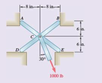
Fig. P6.172
Expert Solution & Answer
Want to see the full answer?
Check out a sample textbook solution
Students have asked these similar questions
Pearson eText
Study Area
mylabmastering.pearson.com
Access Pearson
P Pearson MyLab and Mastering
Problem 14.78
P Course Home
b Answered: HW_02.pdf EE 213-01 > Assignments HW_#...
2 of 8
Document Sharing
User Settings
The spring has a stiffness k = 200 N/m and an
unstretched length of 0.5 m. It is attached to the 4.6-kg
smooth collar and the collar is released from rest at A.
Neglect the size of the collar. (Figure 1)
Part A
Determine the speed of the collar when it reaches B.
Express your answer to three significant figures and include the appropriate units.
Figure
1 of 1
με
VB = Value
Units
Submit
Request Answer
Provide Feedback
?
Review
Next >
Pearson eText
Study Area
Access Pearson
mylabmastering.pearson.com
P Pearson MyLab and Mastering
Problem 15.79
P Course Home
b Answered: HW_02.pdf EE 213-01 > Assignments HW_#...
6 of 8
>
Document Sharing
User Settings
The two disks A and B have a mass of 4 kg and 5 kg,
respectively. They collide with the initial velocities shown.
The coefficient of restitution is e = 0.65. Suppose that
(VA)1 = 6 m/s, (VB)1 = 8 m/s. (Figure 1)
Part A
Determine the magnitude of the velocity of A just after impact.
Express your answer to three significant figures and include the appropriate units.
Figure
1 of 1
μÅ
(VA)2 =
Value
Units
Submit
Request Answer
Part B
?
Review
Determine the angle between the x axis and the velocity of A just after impact, measured clockwise from the negative x axis.
Express your answer in degrees to three significant figures.
ΕΠΙ ΑΣΦ
vec
01
Submit
Request Answer
Part C
?
Determine the magnitude of the velocity of B just after impact.
Express your answer to three significant…
Pearson eText
Study Area
mylabmastering.pearson.com
Access Pearson
P Pearson MyLab and Mastering
Problem 14.78
P Course Home
b Answered: HW_02.pdf EE 213-01 > Assignments HW_#...
2 of 8
Document Sharing
User Settings
The spring has a stiffness k = 200 N/m and an
unstretched length of 0.5 m. It is attached to the 4.6-kg
smooth collar and the collar is released from rest at A.
Neglect the size of the collar. (Figure 1)
Part A
Determine the speed of the collar when it reaches B.
Express your answer to three significant figures and include the appropriate units.
Figure
1 of 1
με
VB = Value
Units
Submit
Request Answer
Provide Feedback
?
Review
Next >
Chapter 6 Solutions
Vector Mechanics for Engineers: Statics
Ch. 6.1 - Using the method of joints, determine the force in...Ch. 6.1 - Using the method of joints, determine the force in...Ch. 6.1 - Using the method of joints, determine the force in...Ch. 6.1 - Using the method of joints, determine the force in...Ch. 6.1 - Using the method of joints, determine the force in...Ch. 6.1 - Using the method of joints, determine the force in...Ch. 6.1 - Using the method of joints, determine the force in...Ch. 6.1 - Using the method of joints, determine the force in...Ch. 6.1 - Using the method of joints, determine the force in...Ch. 6.1 - Determine the force in each member of the truss...
Ch. 6.1 - Determine the force in each member of the Gambrel...Ch. 6.1 - Determine the force in each member of the Howe...Ch. 6.1 - Using the method of joints, determine the force in...Ch. 6.1 - Prob. 6.14PCh. 6.1 - Determine the force in each member of the Warren...Ch. 6.1 - Solve Problem 6.15 assuming that the load applied...Ch. 6.1 - Determine the force in each member of the Pratt...Ch. 6.1 - The truss shown is one of several supporting an...Ch. 6.1 - Determine the force in each member of the Pratt...Ch. 6.1 - Solve Problem 6.19 assuming that the load applied...Ch. 6.1 - Determine the force in each of the members located...Ch. 6.1 - Determine the force in member DE and in each of...Ch. 6.1 - Determine the force in each of the members located...Ch. 6.1 - The portion of truss shown represents the upper...Ch. 6.1 - For the tower and loading of Prob. 6.24 and...Ch. 6.1 - Solve Problem 6.24 assuming that the cables...Ch. 6.1 - Determine the force in each member of the truss...Ch. 6.1 - Determine the force in each member of the truss...Ch. 6.1 - Determine whether the trusses of Problems 6.31a,...Ch. 6.1 - Determine whether the trusses of Problems 6.31b,...Ch. 6.1 - For the given loading, determine the zero-force...Ch. 6.1 - For the given loading, determine the zero-force...Ch. 6.1 - For the given loading, determine the zero-force...Ch. 6.1 - Determine the zero-force members in the truss of...Ch. 6.1 - The truss shown consists of six members and is...Ch. 6.1 - The truss shown consists of six members and is...Ch. 6.1 - The truss shown consists of six members and is...Ch. 6.1 - Prob. 6.38PCh. 6.1 - The truss shown consists of nine members and is...Ch. 6.1 - Solve Prob. 6.39 for P = 0 and Q = (900 N)k. 6.39...Ch. 6.1 - The truss shown consists of 18 members and is...Ch. 6.1 - The truss shown consists of 18 members and is...Ch. 6.2 - Determine the force in members BD and DE of the...Ch. 6.2 - Determine the force in members DG and EG of the...Ch. 6.2 - Determine the force in members BD and CD of the...Ch. 6.2 - Determine the force in members DF and DG of the...Ch. 6.2 - A floor truss is loaded as shown. Determine the...Ch. 6.2 - A floor truss is loaded as shown. Determine the...Ch. 6.2 - Determine the force in members CD and DF of the...Ch. 6.2 - Determine the force in members CE and EF of the...Ch. 6.2 - Determine the force in members DE and DF of the...Ch. 6.2 - Determine the force in members EG and EF of the...Ch. 6.2 - Determine the force in members DF and DE of the...Ch. 6.2 - Determine the force in members CD and CE of the...Ch. 6.2 - A Pratt roof truss is loaded as shown. Determine...Ch. 6.2 - A Pratt roof truss is loaded as shown. Determine...Ch. 6.2 - A Howe scissors roof truss is loaded as shown....Ch. 6.2 - A Howe scissors roof truss is loaded as shown....Ch. 6.2 - Determine the force in members AD, CD, and CE of...Ch. 6.2 - Determine the force in members DG, FG, and FH of...Ch. 6.2 - Determine the force in member GJ of the truss...Ch. 6.2 - Determine the force in members DG and FH of the...Ch. 6.2 - Prob. 6.63PCh. 6.2 - Prob. 6.64PCh. 6.2 - The diagonal members in the center panels of the...Ch. 6.2 - The diagonal members in the center panels of the...Ch. 6.2 - The diagonal members in the center panels of the...Ch. 6.2 - Solve Prob. 6.67 assuming that the 9-kip load has...Ch. 6.2 - Classify each of the structures shown as...Ch. 6.2 - Classify each of the structures shown as...Ch. 6.2 - 6.70 through 6.74 classify as determinate or...Ch. 6.2 - 6.70 through 6.74 classify as determinate or...Ch. 6.2 - 6.70 through 6.74 classify as determinate or...Ch. 6.2 - 6.70 through 6.74 classify as determinate or...Ch. 6.3 - For the frame and loading shown, draw the...Ch. 6.3 - For the frame and loading shown, draw the...Ch. 6.3 - Draw the free-body diagram(s) needed to determine...Ch. 6.3 - Knowing that the pulley has a radius of 0.5 m,...Ch. 6.3 - and 6.76 Determine the force in member BD and the...Ch. 6.3 - Prob. 6.76PCh. 6.3 - For the frame and loading shown, determine the...Ch. 6.3 - Determine the components of all forces acting on...Ch. 6.3 - The hydraulic cylinder CF, which partially...Ch. 6.3 - The hydraulic cylinder CF, which partially...Ch. 6.3 - Determine the components of all forces acting on...Ch. 6.3 - Determine the components of all forces acting on...Ch. 6.3 - Determine the components of the reactions at A and...Ch. 6.3 - Determine the components of the reactions at D and...Ch. 6.3 - Determine the components of the reactions at A and...Ch. 6.3 - Determine the components of the reactions at A and...Ch. 6.3 - Determine the components of the reactions at A and...Ch. 6.3 - The 48-lb load can be moved along the line of...Ch. 6.3 - The 48-lb load is removed and a 288-lb in....Ch. 6.3 - (a) Show that, when a frame supports a pulley at...Ch. 6.3 - Knowing that each pulley has a radius of 250 mm,...Ch. 6.3 - Knowing that the pulley has a radius of 75 mm,...Ch. 6.3 - Prob. 6.93PCh. 6.3 - Prob. 6.94PCh. 6.3 - A trailer weighing 2400 lb is attached to a...Ch. 6.3 - In order to obtain a better weight distribution...Ch. 6.3 - The cab and motor units of the front-end loader...Ch. 6.3 - Solve Problem 6.97 assuming that the 75-kN load...Ch. 6.3 - Knowing that P = 90 lb and Q = 60 lb, determine...Ch. 6.3 - Knowing that P = 90 lb and Q = 60 lb, determine...Ch. 6.3 - For the frame and loading shown, determine the...Ch. 6.3 - For the frame and loading shown, determine the...Ch. 6.3 - Prob. 6.103PCh. 6.3 - Prob. 6.104PCh. 6.3 - For the frame and loading shown, determine the...Ch. 6.3 - Solve Prob. 6.105 assuming that the 6-kN load has...Ch. 6.3 - The axis of the three-hinge arch ABC is a parabola...Ch. 6.3 - The axis of the three-hinge arch ABC is a parabola...Ch. 6.3 - 6.109 and 6.110 Neglecting the effect of friction...Ch. 6.3 - and 6.110 Neglecting the effect of friction at the...Ch. 6.3 - 6.111, 6.112, and 6.113 Members ABC and CDE are...Ch. 6.3 - 6.111, 6.112, and 6.113 Members ABC and CDE are...Ch. 6.3 - 6.111, 6.112, and 6.113 Members ABC and CDE are...Ch. 6.3 - Members ABC and CDE are pin-connected at C and...Ch. 6.3 - Solve Prob. 6.112 assuming that the force P is...Ch. 6.3 - Solve Prob. 6.114 assuming that the force P is...Ch. 6.3 - Four beams, each with a length of 2a, are nailed...Ch. 6.3 - Four beams, each with a length of 3a, are held...Ch. 6.3 - 6.119 through 6.121 Each of the frames shown...Ch. 6.3 - 6.119 through 6.121 Each of the frames shown...Ch. 6.3 - 6.119 through 6.121 Each of the frames shown...Ch. 6.4 - An 84-lb force is applied to the toggle vise at C....Ch. 6.4 - For the system and loading shown, draw the...Ch. 6.4 - A small barrel weighing 60 lb is lifted by a pair...Ch. 6.4 - The position of member ABC is controlled by the...Ch. 6.4 - The shear shown is used to cut and trim...Ch. 6.4 - A 100-lb force directed vertically downward is...Ch. 6.4 - Prob. 6.124PCh. 6.4 - The control rod CE passes through a horizontal...Ch. 6.4 - Solve Prob. 6.125 when (a) = 0, (b) = 6. Fig....Ch. 6.4 - The press shown is used to emboss a small seal at...Ch. 6.4 - The press shown is used to emboss a small seal at...Ch. 6.4 - The pin at B is attached to member ABC and can...Ch. 6.4 - The pin at B is attached to member ABC and can...Ch. 6.4 - Arm ABC is connected by pins to a collar at B and...Ch. 6.4 - Arm ABC is connected by pins to a collar at B and...Ch. 6.4 - The Whitworth mechanism shown is used to produce a...Ch. 6.4 - Solve Prob. 6.133 when (a) = 60, (b) = 90. Fig....Ch. 6.4 - and 6.136 Two rods are connected by a slider block...Ch. 6.4 - and 6.136 Two rods are connected by a slider block...Ch. 6.4 - 6.137 and 6.138 Rod CD is attached to the collar D...Ch. 6.4 - 6.137 and 6.138 Rod CD is attached to the collar D...Ch. 6.4 - Two hydraulic cylinders control the position of...Ch. 6.4 - Two hydraulic cylinders control the position of...Ch. 6.4 - A steel ingot weighing 8000 lb is lifted by a pair...Ch. 6.4 - If the toggle shown is added to the tongs of Prob....Ch. 6.4 - A 9-m length of railroad rail of mass 40 kg/m is...Ch. 6.4 - The gear-pulling assembly shown consists of a...Ch. 6.4 - The pliers shown are used to grip a...Ch. 6.4 - Prob. 6.146PCh. 6.4 - In using the bolt cutter shown, a worker applies...Ch. 6.4 - The upper blade and lower handle of the...Ch. 6.4 - and 6.150 Determine the force P that must be...Ch. 6.4 - and 6.150 Determine the force P that must be...Ch. 6.4 - Because the brace shown must remain in position...Ch. 6.4 - The specialized plumbing wrench shown is used in...Ch. 6.4 - Prob. 6.153PCh. 6.4 - For the frame and loading shown, determine the...Ch. 6.4 - The telescoping arm ABC is used to provide an...Ch. 6.4 - The telescoping arm ABC of Prob. 6.155 can be...Ch. 6.4 - The motion of the backhoe bucket shown is...Ch. 6.4 - Solve Prob. 6.157 assuming that the 2-kip force P...Ch. 6.4 - The gears A and D are rigidly attached to...Ch. 6.4 - In the planetary gear system shown, the radius of...Ch. 6.4 - Two shafts AC and CF, which lie in the vertical xy...Ch. 6.4 - Two shafts AC and CF, which lie in the vertical xy...Ch. 6.4 - The large mechanical tongs shown are used to grab...Ch. 6 - Using the method of joints, determine the force in...Ch. 6 - Using the method of joints, determine the force in...Ch. 6 - A stadium roof truss is loaded as shown. Determine...Ch. 6 - A stadium roof truss is loaded as shown. Determine...Ch. 6 - Determine the components of all forces acting on...Ch. 6 - Determine the components of the reactions at A and...Ch. 6 - Knowing that the pulley has a radius of 50 mm,...Ch. 6 - For the frame and loading shown, determine the...Ch. 6 - For the frame and loading shown, determine the...Ch. 6 - Water pressure in the supply system exerts a...Ch. 6 - A couple M with a magnitude of 1.5 kNm is applied...Ch. 6 - The compound-lever pruning shears shown can be...
Knowledge Booster


Learn more about
Need a deep-dive on the concept behind this application? Look no further. Learn more about this topic, mechanical-engineering and related others by exploring similar questions and additional content below.Similar questions
- Pearson eText Study Area Document Sharing User Settings mylabmastering.pearson.com Access Pearson P Pearson MyLab and Mastering Problem 15.96 Part A In (Figure 1), take m₁ = 3.4 kg and m = 4.8 kg. Figure 1 of 1 P Course Home b Answered: HW_02.pdf EE 213-01 > Assignments HW_#... 7 of 8 Determine the component of the angular momentum Ho of particle A about point O. Express your answer in kilogram-meters squared per second to three significant figures. (Ho) z = -ΜΕ ΑΣΦ vec Submit Request Answer Part B ? kg m2/s Determine the component of the angular momentum Ho of particle B about point O. Suppose that Express your answer in kilogram-meters squared per second to three significant figures. ΜΕ ΑΣΦ vec Symbols (Ho)z = Submit Request Answer Provide Feedback ? kg m2/s Review Next >arrow_forwardPearson eText Study Area Document Sharing User Settings mylabmastering.pearson.com Access Pearson P Pearson MyLab and Mastering Problem 14.69 Part A P Course Home b Answered: HW_02.pdf EE 213-01 > Assignments HW_#... 1 of 8 Review The 5-kg collar has a velocity of 7 m/s to the right when it is at A. It then travels down along the smooth guide shown in (Figure 1). The spring has an unstretched length of 100 mm and B is located just before the end of the curved portion of the rod. Determine the speed of the collar when it reaches point B, which is located just before the end of the curved portion of the rod. Express your answer to three significant figures and include the appropriate units. Figure 1 of 1 με v = Value Units Submit Request Answer Part B ? What is the normal force on the collar at this instant? Express your answer to three significant figures and include the appropriate units. ☐ μÅ ? N = Value Units Submit Request Answer Provide Feedback Next >arrow_forwardPearson eText Study Area mylabmastering.pearson.com Access Pearson P Pearson MyLab and Mastering Problem 15.106 P Course Home b Answered: HW_02.pdf EE 213-01 > Assignments HW_#... 8 of 8 Document Sharing User Settings The two spheres A and B each have a mass of 400 g. The spheres are fixed to the horizontal rods as shown in (Figure 1) and their initial velocity is 2 m/s. The mass of the supporting frame is negligible and it is free to rotate. Neglect the size of the spheres. Part A If a couple moment of M = 0.3 N · m is applied to the frame, determine the speed of the spheres in 3 s. Express your answer to three significant figures and include the appropriate units. Figure 1 of 1 ☐ ? v = Value Units Units input for part A Submit Request Answer Return to Assignment Provide Feedback ■Reviewarrow_forward
- Pearson eText Study Area Access Pearson mylabmastering.pearson.com P Pearson MyLab and Mastering Problem 15.79 P Course Home b Answered: HW_02.pdf EE 213-01 > Assignments HW_#... 6 of 8 > Document Sharing User Settings The two disks A and B have a mass of 4 kg and 5 kg, respectively. They collide with the initial velocities shown. The coefficient of restitution is e = 0.65. Suppose that (VA)1 = 6 m/s, (VB)1 = 8 m/s. (Figure 1) Part A Determine the magnitude of the velocity of A just after impact. Express your answer to three significant figures and include the appropriate units. Figure 1 of 1 μÅ (VA)2 = Value Units Submit Request Answer Part B ? Review Determine the angle between the x axis and the velocity of A just after impact, measured clockwise from the negative x axis. Express your answer in degrees to three significant figures. ΕΠΙ ΑΣΦ vec 01 Submit Request Answer Part C ? Determine the magnitude of the velocity of B just after impact. Express your answer to three significant…arrow_forward40.00 30.00 100.00- 100.00 P = 1000 N A=167 d=140.00 100.00- -b 20.00 200.00 Weld Strength P = 273 N/mm^2 Electrod E60 Safety factor S₁ = 3 Force P = 1000 N Using by SOLIDWORKSarrow_forwardWhat are the reaction forces in A and B?arrow_forward
- Pearson eText Study Area Access Pearson mylabmastering.pearson.com P Pearson MyLab and Mastering Problem 15.6 P Course Home b Answered: HW_02.pdf EE 213-01 > Assignments HW_#... 3 of 8 ■ Review Document Sharing User Settings The jet plane has a mass of 250 Mg and a horizontal velocity of 100 m/s when t = 0. Part A If both engines provide a horizontal thrust which varies as shown in the graph in (Figure 1), determine the plane's velocity in 5 s. Neglect air resistance and the loss of fuel during the motion. Express your answer to three significant figures and include the appropriate units. Figure 1 of 1 > ☐ μÅ ? v = Value Units Submit Request Answer Provide Feedback Next >arrow_forwardAccess Pearson mylabmastering.pearson.com P Pearson MyLab and Mastering Problem 15.43 P Course Home b Answered: HW_02.pdf EE 213-01 > Assignments HW_#... Pearson eText Study Area Document Sharing User Settings The 20-g bullet is travelling at 400 m/s when it becomes embedded in the 2-kg stationary block. The coefficient of kinetic friction between the block and the plane is μk = 0.2. (Figure 1) Part A Determine the distance the block will slide before it stops. Express your answer to three significant figures and include the appropriate units. Figure 1 of 1 με S = Value Units Submit Request Answer Provide Feedback ? 4 of 8 Review Next >arrow_forwardAccess Pearson mylabmastering.pearson.com P Pearson MyLab and Mastering Problem 15.64 P Course Home b Answered: HW_02.pdf EE 213-01 > Assignments HW_#... 5 of 8 Pearson eText Study Area Document Sharing User Settings Ball A has a mass of 3 kg and is moving with a velocity of (VA)1 = 8 m/s when it makes a direct collision with ball B, which has a mass of 2.5 kg and is moving with a velocity of (VB) 1 = 4 m/s. Suppose that e = 0.7. Neglect the size of the balls. (Figure 1) Part A Determine the velocity of A just after the collision. ■Review Express your answer to three significant figures and include the appropriate units. Assume the positive direction is to the right. Figure 1 of 1 ◎ на ? (VA)2= Value Units Submit Request Answer Part B Determine the velocity of B just after the collision. Express your answer to three significant figures and include the appropriate units. Assume the positive direction is to the right. μÅ ? (VB)2= = Value Units Submit Request Answer Provide Feedback Next…arrow_forward
- I only need help with number 3, actually just the theta dot portion. Thanks! I have Vr = 10.39 ft/sarrow_forwardOnly 100% sure experts solve it correct complete solutions okk don't use guidelines or ai answers okk will dislike okkk. Only human experts solved itarrow_forwardAirplanes A and B, flying at constant velocity and at the same altitude, are tracking the eye of hurricane C. The relative velocity of C with respect to A is 300 kph 65.0° South of West, and the relative velocity of C with respect to B is 375 kph 50.0° South of East. A 120.0 km B 1N 1. Determine the relative velocity of B with respect to A. A ground-based radar indicates that hurricane C is moving at a speed of 40.0 kph due north. 2. Determine the velocity of airplane A. 3. Determine the velocity of airplane B. Consider that at the start of the tracking expedition, the distance between the planes is 120.0 km and their initial positions are horizontally collinear. 4. Given the velocities obtained in items 2 and 3, should the pilots of planes A and B be concerned whether the planes will collide at any given time? Prove using pertinent calculations. (Hint: x = x + vt) 0arrow_forward
arrow_back_ios
SEE MORE QUESTIONS
arrow_forward_ios
Recommended textbooks for you
 Elements Of ElectromagneticsMechanical EngineeringISBN:9780190698614Author:Sadiku, Matthew N. O.Publisher:Oxford University Press
 Mechanics of Materials (10th Edition)Mechanical EngineeringISBN:9780134319650Author:Russell C. HibbelerPublisher:PEARSON
 Thermodynamics: An Engineering ApproachMechanical EngineeringISBN:9781259822674Author:Yunus A. Cengel Dr., Michael A. BolesPublisher:McGraw-Hill Education
 Control Systems EngineeringMechanical EngineeringISBN:9781118170519Author:Norman S. NisePublisher:WILEY
 Mechanics of Materials (MindTap Course List)Mechanical EngineeringISBN:9781337093347Author:Barry J. Goodno, James M. GerePublisher:Cengage Learning
 Engineering Mechanics: StaticsMechanical EngineeringISBN:9781118807330Author:James L. Meriam, L. G. Kraige, J. N. BoltonPublisher:WILEY
Elements Of Electromagnetics
Mechanical Engineering
ISBN:9780190698614
Author:Sadiku, Matthew N. O.
Publisher:Oxford University Press
Mechanics of Materials (10th Edition)
Mechanical Engineering
ISBN:9780134319650
Author:Russell C. Hibbeler
Publisher:PEARSON
Thermodynamics: An Engineering Approach
Mechanical Engineering
ISBN:9781259822674
Author:Yunus A. Cengel Dr., Michael A. Boles
Publisher:McGraw-Hill Education
Control Systems Engineering
Mechanical Engineering
ISBN:9781118170519
Author:Norman S. Nise
Publisher:WILEY
Mechanics of Materials (MindTap Course List)
Mechanical Engineering
ISBN:9781337093347
Author:Barry J. Goodno, James M. Gere
Publisher:Cengage Learning
Engineering Mechanics: Statics
Mechanical Engineering
ISBN:9781118807330
Author:James L. Meriam, L. G. Kraige, J. N. Bolton
Publisher:WILEY
Physics 33 - Fluid Statics (1 of 10) Pressure in a Fluid; Author: Michel van Biezen;https://www.youtube.com/watch?v=mzjlAla3H1Q;License: Standard YouTube License, CC-BY