
Videos
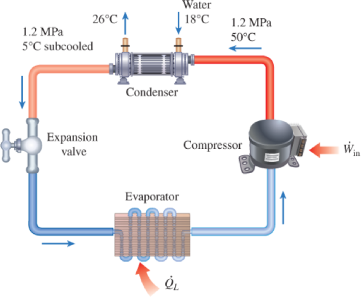
A commercial refrigerator with refrigerant-134a as the working fluid is used to keep the refrigerated space at −35°C by rejecting waste heat to cooling water that enters the condenser at 18°C at a rate of 0.25 kg/s and leaves at 26°C. The refrigerant enters the condenser at 1.2 MPa and 50°C and leaves at the same pressure subcooled by 5°C. If the compressor consumes 3.3 kW of power, determine (a) the mass flow rate of the refrigerant, (b) the refrigeration load, (c) the COP, and (d) the minimum power input to the compressor for the same refrigeration load.
FIGURE P6–107
(a)
The mass flow rate of the refrigerant.
Answer to Problem 107P
The mass flow rate of the refrigerant is
Explanation of Solution
Determine the rate of heat transferred to the water.
Here, the mass flow rate of the water is
Determine the mass flow rate of a refrigerant.
Conclusion:
From the Table A-13, “Superheated refrigerant R-134a” obtain the value of enthalpy of the refrigerant at the inlet of the condenser at the 1.2 MPa of pressure and
From the Table A-13, “Superheated refrigerant R-134a” obtain the value of temperature of the refrigerant at the inlet of the condenser at the 1.2 MPa of pressure as,
Calculate the exit temperature of the refrigerant in the condenser.
Here, the temperature leave from the condenser is
Substitute
Refer to Table A-11, “Saturated refrigerant R-134a”, obtain the below exit enthalpy of the condenser at compressed liquid state on the basis of exit temperature of
Write the formula of interpolation method of two variables.
Here, the variables denote by x and y are temperature and enthalpy of vaporization.
Show the temperature at
| S. No |
Temperature, |
enthalpy of vaporization |
| 1 | ||
| 2 | ||
| 3 |
Calculate exit enthalpy of the condenser at compressed liquid state on the basis of exit temperature of
Substitute
From above calculation the exit enthalpy of the condenser at compressed liquid state on the basis of exit temperature of
Repeat the above Equation (IV) to obtain the value of enthalpy of saturated liquid that entering the inlet of the condenser at the
Repeat the above Equation (IV) to obtain the value of enthalpy of saturated liquid which is leaving the condenser at the
Substitute
Substitute
Thus, the mass flow rate of the refrigerant is
(b)
The refrigeration load of the refrigerator.
Answer to Problem 107P
The refrigeration load of the refrigerator is
Explanation of Solution
Determine the refrigeration load of the refrigerator.
Here, the power input consumed by compressor is
Conclusion:
Substitute
Thus, the refrigeration load of the refrigerator is
(c)
The COP of a reversible refrigerator operating between the same temperature limits.
Answer to Problem 107P
The COP of a reversible refrigerator operating between the same temperature limits is
Explanation of Solution
Determine the coefficient of performance of the refrigerator.
Conclusion:
Substitute
Thus, the COP of a reversible refrigerator operating between the same temperature limits is
(d)
The minimum power input to the compressor.
Answer to Problem 107P
The minimum power input to the compressor is
Explanation of Solution
Determine the maximum coefficient of performance of the reversible refrigerator operating between the same temperature limits.
Here, the temperature of higher temperature body is
Determine the minimum power input to the condenser for the same refrigerator load.
Conclusion:
Substitute
Substitute
Thus, the minimum power input to the compressor is
Want to see more full solutions like this?
Chapter 6 Solutions
THERMODYNAMICS (LL)-W/ACCESS >CUSTOM<


- 1. The maximum and minimum stresses as well as the shear stress seen subjected the piece in plane A-A. Assume it is a cylinder with a diameter of 12.7mm 2. Draw the Mohr circle for the stress state using software. 3. Selection of the material for the prosthesis, which must be analyzed from the point of safety and cost view.arrow_forwardMarrow_forward× Your answer is incorrect. (Manometer) Determine the angle 0 of the inclined tube shown in figure below if the pressure at A is 1 psi greater than that at B. 1ft SG=0.61 十 A Ꮎ 1ft SG=1.0 8.8 ft 0 = Hi 15.20 deg Airarrow_forward
- I don't know how to solve thisarrow_forward1. The maximum and minimum stresses as well as the shear stress seen subjected the piece in plane A-A. Assume it is a cylinder with a diameter of 12.7mm 2. Draw the Mohr circle for the stress state using software. 3. Selection of the material for the prosthesis, which must be analyzed from the point of safety and cost view.arrow_forwardFirst, define the coordinate system XY with its origin at O2 and X-axis passing through O4 asshown above, then based on the provided steps Perform coordinate transformation from XY to xy to get the trajectory of point P. Show all the steps and calcualtionsarrow_forward
- I don't know how to solve thisarrow_forwardQuestion 2 (40 Points) Consider the following double pendulum-like system with links ₁ and 12. The angles 0 and & could have angular velocities ėêk and êk, respectively, where ②k is a unit vector that points out of the page and is perpendicular to x and y. They could also have angular accelerations Ök and êk. The angle is defined relative to the angle 0. The link 12 is a spring and can extend or compress at a rate of 12. It can also have a rate of extension or compression Ï2. li y êr1 êe 12 χ 3 еф er2 ده لج 1) Express the velocity of the mass in terms of the unit vectors ê0, êr1, êø, and êr2, and any extension/contraction of the links (e.g.,. i; and Ï¿) (12 Points) 2) Express the acceleration of the mass in terms of the unit vectors ê¤, ê×1, êp, and êÃ2, and any extension/contraction of the links (e.g.,. İ; and Ï¿) (12 Points) 3) Express the velocity of the mass in terms of unit vectors î and ĵ that point in the x and y directions, respectively. Also include the appropriate,…arrow_forwardprovide step by step solutions for angles teta 3 and teta 4 by the vector loopmethod. Show work in: vector loop, vector equations, solution procedure.arrow_forward
- (Manometer) A tank is constructed of a series of cylinders having diameters of 0.35, 0.30, and 0.20 m as shown in the figure below. The tank contains oil, water, and glycerin and a mercury manometer is attached to the bottom as illustrated. Calculate the manometer reading, h. 0.11 m + SAE 30 Oil 0.13 m + Water 0.10 m Glycerin + 0.10 m Mercury h = marrow_forwardP = A piston having a cross-sectional area of 0.40 m² is located in a cylinder containing water as shown in the figure below. An open U-tube manometer is connected to the cylinder as shown. For h₁ = 83 mm and h = 111 mm what is the value of the applied force, P, acting on the piston? The weight of the piston is negligible. Hi 5597.97 N P Piston Water Mercuryarrow_forwardStudent Name: Student Id: College of Applied Engineering Al-Muzahmiyah Branch Statics (AGE 1330) Section-1483 Quiz-2 Time: 20 minutes Date: 16/02/2025 Q.1. A swinging door that weighs w=400.0N is supported by hinges A and B so that the door can swing about a vertical' axis passing through the hinges (as shown in below figure). The door has a width of b=1.00m and the door slab has a uniform mass density. The hinges are placed symmetrically at the door's edge in such a way that the door's weight is evenly distributed between them. The hinges are separated by distance a=2.00m. Find the forces on the hinges when the door rests half-open. Draw Free body diagram also. [5 marks] [CLO 1.2] Mool b ర a 2.0 m B 1.0 marrow_forward
 Elements Of ElectromagneticsMechanical EngineeringISBN:9780190698614Author:Sadiku, Matthew N. O.Publisher:Oxford University Press
 Mechanics of Materials (10th Edition)Mechanical EngineeringISBN:9780134319650Author:Russell C. HibbelerPublisher:PEARSON
 Thermodynamics: An Engineering ApproachMechanical EngineeringISBN:9781259822674Author:Yunus A. Cengel Dr., Michael A. BolesPublisher:McGraw-Hill Education
 Control Systems EngineeringMechanical EngineeringISBN:9781118170519Author:Norman S. NisePublisher:WILEY
 Mechanics of Materials (MindTap Course List)Mechanical EngineeringISBN:9781337093347Author:Barry J. Goodno, James M. GerePublisher:Cengage Learning
 Engineering Mechanics: StaticsMechanical EngineeringISBN:9781118807330Author:James L. Meriam, L. G. Kraige, J. N. BoltonPublisher:WILEY