
Introductory Circuit Analysis (13th Edition)
13th Edition
ISBN: 9780133923605
Author: Robert L. Boylestad
Publisher: PEARSON
expand_more
expand_more
format_list_bulleted
Concept explainers
Videos
Textbook Question
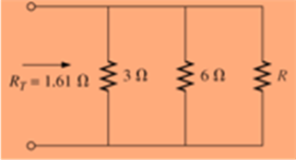
Chapter 6, Problem 7P
The total resistance of each of the configurations in Fig. 6.70, is specified. Find the unknown standard resistance value.
Expert Solution & Answer
Want to see the full answer?
Check out a sample textbook solution
Students have asked these similar questions
Please no AI response.
I have uploaded the rules, please explain step by step and which rule you have applied
I have uploaded the rules, please explain step by step and which rule you have applied
Chapter 6 Solutions
Introductory Circuit Analysis (13th Edition)
Ch. 6 - For each configuration in Fig. 6.64, find the...Ch. 6 - For each configuration of Fig. 6.65, �nd the...Ch. 6 - For the network in Fig. 6.66: Find the elements...Ch. 6 - Find the total resistance for each configuration...Ch. 6 - Find the total resistance for each configuration...Ch. 6 - For each circuit board in Fig. 6.69, �nd the...Ch. 6 - The total resistance of each of the configurations...Ch. 6 - The total resistance for each configuration of...Ch. 6 - For the parallel network in Fig. 6.72, composed of...Ch. 6 - What is the ohmmeter reading for each...
Ch. 6 - Determine R1 for the network in Fig. 6.749.Ch. 6 - For the parallel network in Fig. 6.75: Find the...Ch. 6 - For the network of Fig. 6.76: Find the current...Ch. 6 - Repeat the analysis of Problem 13 for the network...Ch. 6 - For the parallel network in Fig. 6.78: Without...Ch. 6 - Given the information provided in Fig. 6.79, find:...Ch. 6 - Use the information in Fig. 6.80, to calculate:...Ch. 6 - Given the information provided in Fig. 6.81, find...Ch. 6 - For the network of Fig. 6.82, find: The voltage V....Ch. 6 - Using the information provided in Fig. 6.83 find:...Ch. 6 - For the network in Fig. 6.77: Redraw the network...Ch. 6 - For the configuration in Fig. 6.84: Find the total...Ch. 6 - Eight holiday lights are connected in parallel as...Ch. 6 - Determine the power delivered by the dc battery in...Ch. 6 - A portion of a residential service to a home is...Ch. 6 - For the network in Fig. 6.88: Find the current l1....Ch. 6 - Using Kirchhoffs current law, determine the...Ch. 6 - Using Kirchoffs current law, find the unknown...Ch. 6 - Using Kirchhoffs current law, determine the...Ch. 6 - Using the information provided in Fig. 6.92, find...Ch. 6 - Find the unknown quantities for the networks in...Ch. 6 - Find the unknown quantities for the networks of...Ch. 6 - Based solely on the resistor values, determine all...Ch. 6 - Determine one of the unknown currents of Fig....Ch. 6 - For each network of Fig. 6.97, determine the...Ch. 6 - Parts (a) through (e) of this problem should be...Ch. 6 - Find the unknown quantities for the networks in...Ch. 6 - Find resistance R for the network in Fig. 6.100...Ch. 6 - Design the network in Fig. 6.101 such that I2=2I1...Ch. 6 - Assuming identical supplies in Fig. 6.102: Find...Ch. 6 - Assuming identical supplies, determine currents...Ch. 6 - Assuming identical supplies, determine the current...Ch. 6 - For the simple series con�guration in Fig....Ch. 6 - Given the configuration in Fig. 6.106: What is the...Ch. 6 - Based on the measurements of Fig. 6.107, determine...Ch. 6 - Referring to Fig. 6.108, find the voltage Vab...Ch. 6 - The voltage Va for the network in Fig. 6.109, is...Ch. 6 - Prob. 48PCh. 6 - Using PSpice or Multisim, determine the solution...Ch. 6 - Using PSpice or Multisim, determine the solution...
Additional Engineering Textbook Solutions
Find more solutions based on key concepts
Locate the centroid of the area. Prob. 9-17
INTERNATIONAL EDITION---Engineering Mechanics: Statics, 14th edition (SI unit)
How are relationships between tables expressed in a relational database?
Modern Database Management
This optional Google account security feature sends you a message with a code that you must enter, in addition ...
SURVEY OF OPERATING SYSTEMS
What types of coolant are used in vehicles?
Automotive Technology: Principles, Diagnosis, And Service (6th Edition) (halderman Automotive Series)
How does a computers main memory differ from its auxiliary memory?
Java: An Introduction to Problem Solving and Programming (8th Edition)
Which of the following are illegal variable names in Python, and why? x 99bottles july2009 theSalesFigureForFis...
Starting Out with Python (4th Edition)
Knowledge Booster


Learn more about
Need a deep-dive on the concept behind this application? Look no further. Learn more about this topic, electrical-engineering and related others by exploring similar questions and additional content below.Similar questions
- I have uploaded the rules, please explain step by step and which rule you have appliedarrow_forwardUsing the CCS Compiler method to solve this question Write a PIC16F877A program that flash ON the 8-LED's connected to port-B by using two switches connected to port-D (Do & D₁) as shown in figure below, according to the following scenarios: (Hint: Use 500ms delay for each case with 4MHz frequency) 1. When Do=1 then B₁,B3,B7 are ON. 2. When Do 0 then Bo,B2, B4, B5, B6 are ON. 3. When D₁=1 then B4,B,,B6,B7 are ON. 4. When D₁-0 then Bo,B1,B2,B3 are ON.arrow_forwardUse the ramp generator circuit in Fig. B2a to generate the waveform shown in Fig. B2b. Write four equations relating resistors R1, R2, R3, capacitor C and voltages Vs, VR and VA.to the waveform parameters T₁, T, Vcm and Vm- If R = R2 = R3, R₁ = 2R, C = 1 nF, Vcm = 2 V and Vm = 1 V, T₁ = 2 μs and T = 10 μs solve for the values of R, Vs, VR and VA using your equations from part a(i). VR C +VA R3 V₂ Vo мат R1 VsO+ V₁ R₂ Figure B2a Vout Vcm+Vm Vcm Vcm-Vm 0 T₁ T 2T time Figure B2barrow_forward
- The circuit in Figure B1a is a common analogue circuit block. Explain why you would need such a circuit. Draw another circuit in which you use the current flowing in this loop to bias a common source amplifier. This circuit is not ideal for standard CMOS technologies due to threshold shift. Why? Draw an improved version of this circuit to make it better. VDD (W)P MA M3. (), REF (쁜)~ M₁ M2 lout 시~ Rsarrow_forward23bcarrow_forwardDraw the small-signal equivalent circuit of a single transistor amplifier given in figure B1b. Assume the current source to be ideal. Determine the Open-loop transfer function, pole frequency and gain-bandwidth product all in terms of transistor parameters 9m, To and CL. If the load capacitance is 1pF and the necessary unity gain frequency is 600MHz, find the gm for this transistor. V₁ V₁ CLarrow_forward
arrow_back_ios
SEE MORE QUESTIONS
arrow_forward_ios
Recommended textbooks for you
 Introductory Circuit Analysis (13th Edition)Electrical EngineeringISBN:9780133923605Author:Robert L. BoylestadPublisher:PEARSON
 Delmar's Standard Textbook Of ElectricityElectrical EngineeringISBN:9781337900348Author:Stephen L. HermanPublisher:Cengage Learning
 Programmable Logic ControllersElectrical EngineeringISBN:9780073373843Author:Frank D. PetruzellaPublisher:McGraw-Hill Education
 Fundamentals of Electric CircuitsElectrical EngineeringISBN:9780078028229Author:Charles K Alexander, Matthew SadikuPublisher:McGraw-Hill Education
 Electric Circuits. (11th Edition)Electrical EngineeringISBN:9780134746968Author:James W. Nilsson, Susan RiedelPublisher:PEARSON
 Engineering ElectromagneticsElectrical EngineeringISBN:9780078028151Author:Hayt, William H. (william Hart), Jr, BUCK, John A.Publisher:Mcgraw-hill Education,
Introductory Circuit Analysis (13th Edition)
Electrical Engineering
ISBN:9780133923605
Author:Robert L. Boylestad
Publisher:PEARSON
Delmar's Standard Textbook Of Electricity
Electrical Engineering
ISBN:9781337900348
Author:Stephen L. Herman
Publisher:Cengage Learning
Programmable Logic Controllers
Electrical Engineering
ISBN:9780073373843
Author:Frank D. Petruzella
Publisher:McGraw-Hill Education
Fundamentals of Electric Circuits
Electrical Engineering
ISBN:9780078028229
Author:Charles K Alexander, Matthew Sadiku
Publisher:McGraw-Hill Education
Electric Circuits. (11th Edition)
Electrical Engineering
ISBN:9780134746968
Author:James W. Nilsson, Susan Riedel
Publisher:PEARSON
Engineering Electromagnetics
Electrical Engineering
ISBN:9780078028151
Author:Hayt, William H. (william Hart), Jr, BUCK, John A.
Publisher:Mcgraw-hill Education,
Kirchhoff's Rules of Electrical Circuits; Author: Flipping Physics;https://www.youtube.com/watch?v=d0O-KUKP4nM;License: Standard YouTube License, CC-BY