
Introductory Circuit Analysis (13th Edition)
13th Edition
ISBN: 9780133923605
Author: Robert L. Boylestad
Publisher: PEARSON
expand_more
expand_more
format_list_bulleted
Concept explainers
Videos
Textbook Question
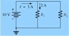
Chapter 6, Problem 31P
Find the unknown quantities for the networks in Fig. 6.93, using the information provided.
Expert Solution & Answer
Want to see the full answer?
Check out a sample textbook solution
Students have asked these similar questions
- From these 2 truth tables (A and B), develop- The unsimplified function- Karnaugh's map- Simplified function- The schematic design of the circuit from the simplified function- The Circuit in Tinkercad from the simplified function (include Screenshots and Link circuits in Tinkercad)
Build the respective truth tables, the Schematic Design of the unsimplified circuit, only with NAND logic gates, based on the following boolean functions: a) (X * Y)’ + Zb) ((A + B) * Z)’
Develop the steps of Analog Digital Conversion (ADC) of the following analog signal, considering the signal sampling analog (gray square values), the quantization of the signal itself, the encoding of the quantization result in binary code and the resulting pulse train.
Chapter 6 Solutions
Introductory Circuit Analysis (13th Edition)
Ch. 6 - For each configuration in Fig. 6.64, find the...Ch. 6 - For each configuration of Fig. 6.65, �nd the...Ch. 6 - For the network in Fig. 6.66: Find the elements...Ch. 6 - Find the total resistance for each configuration...Ch. 6 - Find the total resistance for each configuration...Ch. 6 - For each circuit board in Fig. 6.69, �nd the...Ch. 6 - The total resistance of each of the configurations...Ch. 6 - The total resistance for each configuration of...Ch. 6 - For the parallel network in Fig. 6.72, composed of...Ch. 6 - What is the ohmmeter reading for each...
Ch. 6 - Determine R1 for the network in Fig. 6.749.Ch. 6 - For the parallel network in Fig. 6.75: Find the...Ch. 6 - For the network of Fig. 6.76: Find the current...Ch. 6 - Repeat the analysis of Problem 13 for the network...Ch. 6 - For the parallel network in Fig. 6.78: Without...Ch. 6 - Given the information provided in Fig. 6.79, find:...Ch. 6 - Use the information in Fig. 6.80, to calculate:...Ch. 6 - Given the information provided in Fig. 6.81, find...Ch. 6 - For the network of Fig. 6.82, find: The voltage V....Ch. 6 - Using the information provided in Fig. 6.83 find:...Ch. 6 - For the network in Fig. 6.77: Redraw the network...Ch. 6 - For the configuration in Fig. 6.84: Find the total...Ch. 6 - Eight holiday lights are connected in parallel as...Ch. 6 - Determine the power delivered by the dc battery in...Ch. 6 - A portion of a residential service to a home is...Ch. 6 - For the network in Fig. 6.88: Find the current l1....Ch. 6 - Using Kirchhoffs current law, determine the...Ch. 6 - Using Kirchoffs current law, find the unknown...Ch. 6 - Using Kirchhoffs current law, determine the...Ch. 6 - Using the information provided in Fig. 6.92, find...Ch. 6 - Find the unknown quantities for the networks in...Ch. 6 - Find the unknown quantities for the networks of...Ch. 6 - Based solely on the resistor values, determine all...Ch. 6 - Determine one of the unknown currents of Fig....Ch. 6 - For each network of Fig. 6.97, determine the...Ch. 6 - Parts (a) through (e) of this problem should be...Ch. 6 - Find the unknown quantities for the networks in...Ch. 6 - Find resistance R for the network in Fig. 6.100...Ch. 6 - Design the network in Fig. 6.101 such that I2=2I1...Ch. 6 - Assuming identical supplies in Fig. 6.102: Find...Ch. 6 - Assuming identical supplies, determine currents...Ch. 6 - Assuming identical supplies, determine the current...Ch. 6 - For the simple series con�guration in Fig....Ch. 6 - Given the configuration in Fig. 6.106: What is the...Ch. 6 - Based on the measurements of Fig. 6.107, determine...Ch. 6 - Referring to Fig. 6.108, find the voltage Vab...Ch. 6 - The voltage Va for the network in Fig. 6.109, is...Ch. 6 - Prob. 48PCh. 6 - Using PSpice or Multisim, determine the solution...Ch. 6 - Using PSpice or Multisim, determine the solution...
Knowledge Booster


Learn more about
Need a deep-dive on the concept behind this application? Look no further. Learn more about this topic, electrical-engineering and related others by exploring similar questions and additional content below.Similar questions
- Determine the values of the necessary resistances, design and run the circuit in TINKERCAD for an integrated 555 Astable with T1 (on time) of 8 seconds and a T2 (off time) of 4 seconds. The value for capacitor C1 must be 100 uF (0.0001 F).arrow_forward- What are Flip Flop circuits used for? Explain the operation of an R-S Flip Flop.- What function do Multiplexers or MUXs perform?arrow_forward- What function do Demultiplexers or DEMUX perform?- According to the implementation of automation circuits with ARDUINO boards, what would they be, Conceptually, the main components of any system of automation? Draw a representative schematic or block diagram.arrow_forward
- Solve problems 5.2 in detail and thank youarrow_forward5.1 Determine the three zone settings for the relay Rab in the system shown in Figure 5.26. The system nominal voltage is 138 kV, and the positive sequence impedances for the various elements are given in the figure. The transformer impedance is given in ohms as viewed from the 138 kV side. Assume that the maximum load at the relay site is 120 MVA, and select a CT ratio accordingly. The available distance relay has zone 1 and zone 2 settings from 0.2 to 10 2, and zone 3 settings from 0.5 to 40 2, in increments of 0.1 2. The angle of maximum torque can be adjusted to 75° or 80°. Remember that the zone 3 of the relay must back up the line BC, as well as the transformer. A Rab (3+j40) B (2+ j50) (0+j9) с Fu D Figure 5.26 System for problem 5.1arrow_forwardPlease solve question 4.7 in detail and thank youarrow_forward
- Solve in detail to understandarrow_forwardE2.6 Consider the following neural network. Input Sat. Linear Layer Linear Layer purelin(Wa+b) Sketch the following responses (plot the indicated variable versus p for (-3arrow_forwardE2.3 Given a two-input neuron with the following weight matrix and input vector: w=[32] and p = [-5 7], we would like to have an output of 0.5. Do you suppose that there is a combination of bias and transfer function that might allow this? i. Is there a transfer function from Table 2.1 that will do the job if the bias is zero? ii. Is there a bias that will do the job if the linear transfer function is used? If yes, what is it? iii. Is there a bias that will do the job if a log-sigmoid transfer function is used? Again, if yes, what is it? iv. Is there a bias that will do the job if a symmetrical hard limit transfer function is used? Again, if yes, what is it?arrow_forwardE2.2 Consider a single-input neuron with a bias. We would like the output to be -1 for inputs less than 3 and +1 for inputs greater than or equal to 3. i. What kind of a transfer function is required? ii. What bias would you suggest? Is your bias in any way related to the input weight? If yes, how? iii. Summarize your network by naming the transfer function and stating the bias and the weight. Draw a diagram of the network.arrow_forwardE2.1 A single input neuron has a weight of 1.3 and a bias of 3.0. What possible kinds of transfer functions, from Table 2.1, could this neuron have, if its output is given below. In each case, give the value of the input that would produce these outputs. i. 1.6 ii. 1.0 iii. 0.9963 iv. -1.0arrow_forwardQ2. The slew rate of an amplifier can cause signal distortion at its output if wrongly chosen. State the criterion for selecting the slew rate of an amplifier to avoid signal distortion. A step signal of 5 mV is applied to an inverting amplifier shown in Figure 2, which has a slew rate of 0.05 V/us. Estimate the time required for the output voltage of the amplifier to reach within 10% of its final value. If the input to Figure 2 is a sinusoidal signal of 0.02 sin(2πft) V, determine the maximum frequency that can be applied to the circuit without causing signal distortion due to the limitation of its slew rate (0.05 V/µs). In order to minimise the output offset voltage of Figure 2, a compensating resistor should be added to Figure 2. Draw a modified circuit diagram that includes the compensating resistor. Determine the appropriate value for the compensating resistor. V₁ 2 ΚΩ 100 ΚΩ +arrow_forwardarrow_back_iosSEE MORE QUESTIONSarrow_forward_ios
Recommended textbooks for you
 Introductory Circuit Analysis (13th Edition)Electrical EngineeringISBN:9780133923605Author:Robert L. BoylestadPublisher:PEARSON
 Delmar's Standard Textbook Of ElectricityElectrical EngineeringISBN:9781337900348Author:Stephen L. HermanPublisher:Cengage Learning
 Programmable Logic ControllersElectrical EngineeringISBN:9780073373843Author:Frank D. PetruzellaPublisher:McGraw-Hill Education
 Fundamentals of Electric CircuitsElectrical EngineeringISBN:9780078028229Author:Charles K Alexander, Matthew SadikuPublisher:McGraw-Hill Education
 Electric Circuits. (11th Edition)Electrical EngineeringISBN:9780134746968Author:James W. Nilsson, Susan RiedelPublisher:PEARSON
 Engineering ElectromagneticsElectrical EngineeringISBN:9780078028151Author:Hayt, William H. (william Hart), Jr, BUCK, John A.Publisher:Mcgraw-hill Education,
Introductory Circuit Analysis (13th Edition)
Electrical Engineering
ISBN:9780133923605
Author:Robert L. Boylestad
Publisher:PEARSON
Delmar's Standard Textbook Of Electricity
Electrical Engineering
ISBN:9781337900348
Author:Stephen L. Herman
Publisher:Cengage Learning
Programmable Logic Controllers
Electrical Engineering
ISBN:9780073373843
Author:Frank D. Petruzella
Publisher:McGraw-Hill Education
Fundamentals of Electric Circuits
Electrical Engineering
ISBN:9780078028229
Author:Charles K Alexander, Matthew Sadiku
Publisher:McGraw-Hill Education
Electric Circuits. (11th Edition)
Electrical Engineering
ISBN:9780134746968
Author:James W. Nilsson, Susan Riedel
Publisher:PEARSON
Engineering Electromagnetics
Electrical Engineering
ISBN:9780078028151
Author:Hayt, William H. (william Hart), Jr, BUCK, John A.
Publisher:Mcgraw-hill Education,
Kirchhoff's Rules of Electrical Circuits; Author: Flipping Physics;https://www.youtube.com/watch?v=d0O-KUKP4nM;License: Standard YouTube License, CC-BY