
Introductory Circuit Analysis (13th Edition)
13th Edition
ISBN: 9780133923605
Author: Robert L. Boylestad
Publisher: PEARSON
expand_more
expand_more
format_list_bulleted
Concept explainers
Videos
Textbook Question
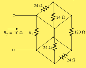
Chapter 6, Problem 11P
Determine
Expert Solution & Answer

Trending nowThis is a popular solution!

Students have asked these similar questions
Prelab Information
Laboratory Preliminary Discussion
Second-order RLC Circuit Analysis
The second-order RLC circuit shown in figure 1 below represents all voltages and impedances as functions of the complex
variable, s. Note, of course, that the impedances associated with R, RL, and Rs are constant independent of frequency, so the 's'
notation is omitted. Again, one of the advantages of s-domain analysis is that we can apply all of the circuit analysis techniques
learned for AC and DC circuits.
ZI(s)
Zc(s)
Rs
w
RL
ww
+
+
VRS(S)
VRL(S)
VL(s)
Vc(s)
VR(S)
R
Vs(s)
Figure 1: A second-order RLC circuit represented in the s-domain.
To generate the s-domain expression for the output voltage, Vout(s) = VR(S), for the circuit shown in figure 1, we can apply voltage
division in the s-domain as shown in equation 1 below. For equation 1 we define the following circuit parameters.
RT=RS + RL + R where: R₁ = Total series resistance
Rs Signal generator output resistance (fixed)
Inductor internal…
Can you show how the correct answer was found.
For the circuit shown in Figure (1). Solve the following: (
A. What type of logic does it represent?
C. Explain the function of D1.
B. What type of logic family does it belong to?
D. Explain the importance of DL.
E. How many stages it has? Explain the function of each one.
F. Construct the truth table and explain it briefly.
G.How can you convert this circuit to an open collector form? Explain and sketch it.
H.How can you convert this circuit to a tri-state form? Explain and sketch it.
I. How can you prevent the transistors from being saturated?
J. Which transistor should be modified to convert this circuit to a 4-inputs NAND?
Explain and sketch it.
K.Convert this circuit to a 2-inputs NOR gate and draw it.
R-1200
R-4.2K
R-1.5K
R-IK
Figure (1)
lour
e Your
Chapter 6 Solutions
Introductory Circuit Analysis (13th Edition)
Ch. 6 - For each configuration in Fig. 6.64, find the...Ch. 6 - For each configuration of Fig. 6.65, �nd the...Ch. 6 - For the network in Fig. 6.66: Find the elements...Ch. 6 - Find the total resistance for each configuration...Ch. 6 - Find the total resistance for each configuration...Ch. 6 - For each circuit board in Fig. 6.69, �nd the...Ch. 6 - The total resistance of each of the configurations...Ch. 6 - The total resistance for each configuration of...Ch. 6 - For the parallel network in Fig. 6.72, composed of...Ch. 6 - What is the ohmmeter reading for each...
Ch. 6 - Determine R1 for the network in Fig. 6.749.Ch. 6 - For the parallel network in Fig. 6.75: Find the...Ch. 6 - For the network of Fig. 6.76: Find the current...Ch. 6 - Repeat the analysis of Problem 13 for the network...Ch. 6 - For the parallel network in Fig. 6.78: Without...Ch. 6 - Given the information provided in Fig. 6.79, find:...Ch. 6 - Use the information in Fig. 6.80, to calculate:...Ch. 6 - Given the information provided in Fig. 6.81, find...Ch. 6 - For the network of Fig. 6.82, find: The voltage V....Ch. 6 - Using the information provided in Fig. 6.83 find:...Ch. 6 - For the network in Fig. 6.77: Redraw the network...Ch. 6 - For the configuration in Fig. 6.84: Find the total...Ch. 6 - Eight holiday lights are connected in parallel as...Ch. 6 - Determine the power delivered by the dc battery in...Ch. 6 - A portion of a residential service to a home is...Ch. 6 - For the network in Fig. 6.88: Find the current l1....Ch. 6 - Using Kirchhoffs current law, determine the...Ch. 6 - Using Kirchoffs current law, find the unknown...Ch. 6 - Using Kirchhoffs current law, determine the...Ch. 6 - Using the information provided in Fig. 6.92, find...Ch. 6 - Find the unknown quantities for the networks in...Ch. 6 - Find the unknown quantities for the networks of...Ch. 6 - Based solely on the resistor values, determine all...Ch. 6 - Determine one of the unknown currents of Fig....Ch. 6 - For each network of Fig. 6.97, determine the...Ch. 6 - Parts (a) through (e) of this problem should be...Ch. 6 - Find the unknown quantities for the networks in...Ch. 6 - Find resistance R for the network in Fig. 6.100...Ch. 6 - Design the network in Fig. 6.101 such that I2=2I1...Ch. 6 - Assuming identical supplies in Fig. 6.102: Find...Ch. 6 - Assuming identical supplies, determine currents...Ch. 6 - Assuming identical supplies, determine the current...Ch. 6 - For the simple series con�guration in Fig....Ch. 6 - Given the configuration in Fig. 6.106: What is the...Ch. 6 - Based on the measurements of Fig. 6.107, determine...Ch. 6 - Referring to Fig. 6.108, find the voltage Vab...Ch. 6 - The voltage Va for the network in Fig. 6.109, is...Ch. 6 - Prob. 48PCh. 6 - Using PSpice or Multisim, determine the solution...Ch. 6 - Using PSpice or Multisim, determine the solution...
Additional Engineering Textbook Solutions
Find more solutions based on key concepts
A nozzle at A discharges water with an initial velocity of 36 ft/s at an angle with the horizontal. Determine ...
Vector Mechanics For Engineers
17–1C A high-speed aircraft is cruising in still air. How does the temperature of air at the nose of the aircra...
Thermodynamics: An Engineering Approach
Assume a telephone signal travels through a cable at two-thirds the speed of light. How long does it take the s...
Electric Circuits. (11th Edition)
Why is the study of database technology important?
Database Concepts (8th Edition)
Comprehension Check 7-14
The power absorbed by a resistor can be given by P = I2R, where P is power in units of...
Thinking Like an Engineer: An Active Learning Approach (4th Edition)
How is the hydrodynamic entry length defined for flow in a pipe? Is the entry length longer in laminar or turbu...
Fluid Mechanics: Fundamentals and Applications
Knowledge Booster


Learn more about
Need a deep-dive on the concept behind this application? Look no further. Learn more about this topic, electrical-engineering and related others by exploring similar questions and additional content below.Similar questions
- E. How many stages it has? Explain the function of each one. F. Construct the truth table and explain it briefly. G.How can you convert this circuit to an open collector form? Explain and sketch it. H.How can you convert this circuit to a tri-state form? Explain and sketch it. I. How can you prevent the transistors from being saturated? J. Which transistor should be modified to convert this circuit to a 4-inputs NAND? Explain and sketch it. K.Convert this circuit to a 2-inputs NOR gate and draw it. R-4.2K W R-1200 R-1.5K R-IK Figure (1) JOUT e Yourarrow_forward1. Determine the z-transform, including the region of convergence (ROC), of the following signals: a)x[n={3,0,0,0,0,51-4} b) x2[n] = ((1/3)^n ,n ≥0 2", n < 0 c) X3[n]= (1/3)^n- 2", n ≥ 0 0, n < 0arrow_forwardUse ECL configuration to realize a 2-inputs OR /NOR gate and verify its function using the truth table, showing the state of each transistor in the circuit. Assume Vcc 5V, VEE-0V & VREF=1.5V.arrow_forward
- Twenty-five signals, ten of them have 3.4 kHz bandwidth, the other have bandwidth of 5 kHz are FDM/TDM multiplexed then modulated by an RF carrier of 800 kHz using AM modulator: Calculate minimum multiplexing and transmission bandwidths. Calculate the guard band (BWGuard) to be added between each two signals and below the first one to result a multiplexing bandwidth of 131.5 kHzarrow_forwardAn FDM is used to multiplex two groups of signals using AM-SSB, the first group contains 25 speech signals, each has maximum frequency of 4 kHz, the second group contains 15 music signals, each has maximum frequency of 10 kHz. A guard bandwidth of 500 Hz is used between each two signals and before the first one. 1. Find the BWmultiplexing 2. Find the BWtransmission if the multiplexing signal is modulated using AM-DSB-LC.arrow_forwardA single tone is modulated using FM transmitter. The SNR; at the input of the demodulator Is 20 dB. If the maximum frequency of the modulating signal is 4 kHz, and the maximum frequency deviation is 12 kHz, find the SNR, and the bandwidth (using Carson rule) at the following conditions: 1. For the given values of fm and Af. 2. If the amplitude of the modulating signal is increased by 80%. 3. If the amplitude of the modulating signal is decreased by 50%, and frequency of modulating signal is increased by 50%.arrow_forward
- FM station of 100 MHz carrier frequency modulated by a 20 kHz sinusoid with an amplitude of 10 volt, so that the peak frequency deviation is 25 kHz determine: 1) The BW of the FM signal. 2) The approximated BW if the modulating signal amplitude is increased to 50 volt. 3) The approximated BW if the modulating signal frequency is increased by 70%. 4) The amplitude of the modulating signal if the BW is 65 kHz.arrow_forwardb) The joint probability function for the random variables X and Y is given in Table below. Find a) the marginal probability function of X and Y. P(Y/X) and P(X/Y). c) P(X ≥ 2, Y ≤ 2) y 1 2 3 10.05 0.05 0.1 P(X, Y) = X 20.05 0.1 0.35 3 0 0.2 0.1arrow_forwardSuppose a random variable X as pmf / Px (x) = { %, x = 1, 2, 3, 0, otherwise. find constand c ①P(X = 1), P(X 7,2), PC1 3) C CDFarrow_forward
- Suppose that a coin is tossed three so that the sample space is Let X represent the number of heads that can come up. i) Find the probability function corresponding to the random variable X. Assuming that the coin is fair ii) Find the distribution function for the random variable X. iii) Obtain its graph.arrow_forwardQ9 A single-phase transformer, 2500 / 250 V, 50 kVA, 50 Hz has the following parameters, the Primary and secondary resistances are 0.8 ohm and 0.012 ohm respectively, the primary and secondary reactance are 4 ohm and 0.04 ohm respectively and the transformer gives 96% maximum efficiency at 75% full-load. The magnetizing component of-load current is 1.2 A on 2500 V side. 1- Draw the equivalent circuit referred to primary (H.V side) and inserts all the values in it 2- Find out Ammeter, voltmeter and wattmeter readings on open-circuit and short-circuit test. If supply is given to 2500 V side in both cases. Ans. O.C. Test (Vo= 2500 V, lo=1.24 A, Wo=781.25 w) S.C. Test (Vsc =164.924 V, Isc =20 A, Wsc =800 w )arrow_forwardQ2-A)- Enumerate the various losses in transformer. Explain how each loss varies with (Load current, supply voltage). B)- Draw the pharos diagram at load on primary side.arrow_forward
arrow_back_ios
SEE MORE QUESTIONS
arrow_forward_ios
Recommended textbooks for you
 Introductory Circuit Analysis (13th Edition)Electrical EngineeringISBN:9780133923605Author:Robert L. BoylestadPublisher:PEARSON
 Delmar's Standard Textbook Of ElectricityElectrical EngineeringISBN:9781337900348Author:Stephen L. HermanPublisher:Cengage Learning
 Programmable Logic ControllersElectrical EngineeringISBN:9780073373843Author:Frank D. PetruzellaPublisher:McGraw-Hill Education
 Fundamentals of Electric CircuitsElectrical EngineeringISBN:9780078028229Author:Charles K Alexander, Matthew SadikuPublisher:McGraw-Hill Education
 Electric Circuits. (11th Edition)Electrical EngineeringISBN:9780134746968Author:James W. Nilsson, Susan RiedelPublisher:PEARSON
 Engineering ElectromagneticsElectrical EngineeringISBN:9780078028151Author:Hayt, William H. (william Hart), Jr, BUCK, John A.Publisher:Mcgraw-hill Education,
Introductory Circuit Analysis (13th Edition)
Electrical Engineering
ISBN:9780133923605
Author:Robert L. Boylestad
Publisher:PEARSON
Delmar's Standard Textbook Of Electricity
Electrical Engineering
ISBN:9781337900348
Author:Stephen L. Herman
Publisher:Cengage Learning
Programmable Logic Controllers
Electrical Engineering
ISBN:9780073373843
Author:Frank D. Petruzella
Publisher:McGraw-Hill Education
Fundamentals of Electric Circuits
Electrical Engineering
ISBN:9780078028229
Author:Charles K Alexander, Matthew Sadiku
Publisher:McGraw-Hill Education
Electric Circuits. (11th Edition)
Electrical Engineering
ISBN:9780134746968
Author:James W. Nilsson, Susan Riedel
Publisher:PEARSON
Engineering Electromagnetics
Electrical Engineering
ISBN:9780078028151
Author:Hayt, William H. (william Hart), Jr, BUCK, John A.
Publisher:Mcgraw-hill Education,
Kirchhoff's Rules of Electrical Circuits; Author: Flipping Physics;https://www.youtube.com/watch?v=d0O-KUKP4nM;License: Standard YouTube License, CC-BY