
Introductory Circuit Analysis (13th Edition)
13th Edition
ISBN: 9780133923605
Author: Robert L. Boylestad
Publisher: PEARSON
expand_more
expand_more
format_list_bulleted
Concept explainers
Videos
Textbook Question
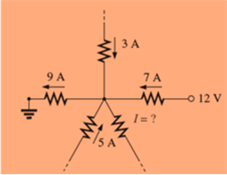
Chapter 6, Problem 28P
Using Kirchoff’s current law, find the unknown currents for the complex configurations in Fig. 6.90.
Expert Solution & Answer
Want to see the full answer?
Check out a sample textbook solution
Students have asked these similar questions
15) Complex numbers 21 and 22 are given by
Δ Δ Δ
Z₁ = 21-60°
22 = 5/45°
Determine in polar form:
Z, Z₂
b) 21/22
Z₁
C) Z, Z₂
dz
2
zz
Z
f) JZ ₂
9)
z, (z₂-z₁) *
~22/(Z1+Zz)
FAAAAAA
A
form:
Express The following Complex numbers in rectangular
№ 2,
b) Z₂ = -3e-jπ/4
c) 23 = √ 3 e
d 24
11
-j
25 =
==J
3
-4
2
-j3π/4
f) 26 = (2 + j)
9) 2₂ = (3-j2)³
g
D
27
AAA
D
A
35
0) Express The following complex numbers in polar form:
az₁ = 3+ j4
2
b) 2₂ = -6+j8
C) 23 = 6j4
Z4=j2
d) 24 = j2
e) 25 = (2+ j)²
3
4) 26 = (3-j2) ³
JZ7 = (1+j) ½/2
27
D
D
D
D
D
AA
D
AAL
Chapter 6 Solutions
Introductory Circuit Analysis (13th Edition)
Ch. 6 - For each configuration in Fig. 6.64, find the...Ch. 6 - For each configuration of Fig. 6.65, �nd the...Ch. 6 - For the network in Fig. 6.66: Find the elements...Ch. 6 - Find the total resistance for each configuration...Ch. 6 - Find the total resistance for each configuration...Ch. 6 - For each circuit board in Fig. 6.69, �nd the...Ch. 6 - The total resistance of each of the configurations...Ch. 6 - The total resistance for each configuration of...Ch. 6 - For the parallel network in Fig. 6.72, composed of...Ch. 6 - What is the ohmmeter reading for each...
Ch. 6 - Determine R1 for the network in Fig. 6.749.Ch. 6 - For the parallel network in Fig. 6.75: Find the...Ch. 6 - For the network of Fig. 6.76: Find the current...Ch. 6 - Repeat the analysis of Problem 13 for the network...Ch. 6 - For the parallel network in Fig. 6.78: Without...Ch. 6 - Given the information provided in Fig. 6.79, find:...Ch. 6 - Use the information in Fig. 6.80, to calculate:...Ch. 6 - Given the information provided in Fig. 6.81, find...Ch. 6 - For the network of Fig. 6.82, find: The voltage V....Ch. 6 - Using the information provided in Fig. 6.83 find:...Ch. 6 - For the network in Fig. 6.77: Redraw the network...Ch. 6 - For the configuration in Fig. 6.84: Find the total...Ch. 6 - Eight holiday lights are connected in parallel as...Ch. 6 - Determine the power delivered by the dc battery in...Ch. 6 - A portion of a residential service to a home is...Ch. 6 - For the network in Fig. 6.88: Find the current l1....Ch. 6 - Using Kirchhoffs current law, determine the...Ch. 6 - Using Kirchoffs current law, find the unknown...Ch. 6 - Using Kirchhoffs current law, determine the...Ch. 6 - Using the information provided in Fig. 6.92, find...Ch. 6 - Find the unknown quantities for the networks in...Ch. 6 - Find the unknown quantities for the networks of...Ch. 6 - Based solely on the resistor values, determine all...Ch. 6 - Determine one of the unknown currents of Fig....Ch. 6 - For each network of Fig. 6.97, determine the...Ch. 6 - Parts (a) through (e) of this problem should be...Ch. 6 - Find the unknown quantities for the networks in...Ch. 6 - Find resistance R for the network in Fig. 6.100...Ch. 6 - Design the network in Fig. 6.101 such that I2=2I1...Ch. 6 - Assuming identical supplies in Fig. 6.102: Find...Ch. 6 - Assuming identical supplies, determine currents...Ch. 6 - Assuming identical supplies, determine the current...Ch. 6 - For the simple series con�guration in Fig....Ch. 6 - Given the configuration in Fig. 6.106: What is the...Ch. 6 - Based on the measurements of Fig. 6.107, determine...Ch. 6 - Referring to Fig. 6.108, find the voltage Vab...Ch. 6 - The voltage Va for the network in Fig. 6.109, is...Ch. 6 - Prob. 48PCh. 6 - Using PSpice or Multisim, determine the solution...Ch. 6 - Using PSpice or Multisim, determine the solution...
Additional Engineering Textbook Solutions
Find more solutions based on key concepts
A nozzle at A discharges water with an initial velocity of 36 ft/s at an angle with the horizontal. Determine ...
Vector Mechanics For Engineers
The job of the _____ is to fetch instructions, carry out the operations commanded by the instructions, and prod...
Starting Out With Visual Basic (8th Edition)
The solid steel shaft AC has a diameter of 25 mm and is supported by smooth bearings at D and E. It is coupled ...
Mechanics of Materials (10th Edition)
Assume a telephone signal travels through a cable at two-thirds the speed of light. How long does it take the s...
Electric Circuits. (11th Edition)
What are the design issues for character string types?
Concepts Of Programming Languages
17–1C A high-speed aircraft is cruising in still air. How does the temperature of air at the nose of the aircra...
Thermodynamics: An Engineering Approach
Knowledge Booster


Learn more about
Need a deep-dive on the concept behind this application? Look no further. Learn more about this topic, electrical-engineering and related others by exploring similar questions and additional content below.Similar questions
- 21) Determine. The phasor counterparts of the following sinusoidal functions: (a) V₁ (t) = 4 cos (377-30°) V (B) V₂ (t) = -2sin (8T x 10"+ + 18°) V e) V3 (t) = 3 sin (1000 + + 53°)-4c05 (1000 t -17°) v AAA AAAAAarrow_forwardI need help with this problem and an explanation of the solution for the image described below. (Introduction to Signals and Systems)arrow_forwardTutorial - Design of Common-Gate (CG) Amplifier Design a common-gate NMOS amplifier with the following parameters: Supply Voltage (VDD): 10 V ⚫Threshold Voltage (Vth): 2 V •Overdrive Voltage (Vov) = VGS-Vth: 1 V • Desired Voltage Gain Av: 10 V/V • Transconductance gm: to be determined •Ensure that the NMOS operates in the saturation region. ⚫ Design Vos to ensure saturation and enough voltage swing. C₁ Vin +VDD RD C₂ V out Rs WI RLarrow_forward
- NEED HANDWRITTEN SOLUTION DO NOT USE CHATGPT OR AIarrow_forwardDetermine the response y(n), n≥0 of the system described by the second order difference equation: y(n)-4y(n-1)+4y(n-2)=x(n)-x(n-1) when the input is x(n)=(−1)" u(n) and the initial conditions are y(-1)=y(-2)=0.arrow_forwardConsider a Continuous- time LTI System described by y' (+)+ nycH) = x() find yet for a) x(+)o ē+4(H) b) X(+) = u(+). c) X(H= 5(+)arrow_forward
- Find the Thevenin equivalent representation of the circuit given to the left of the nodes a and b. Find Vth and Rth and draw the equivalent Thevenin circuit. For Rth use a 1 volt test source as your method.arrow_forwardR(s) + E(s) 100(s+2)(s+6) s(s+3)(s+4) C(s)arrow_forwardEXAMPLE 3.6 Determine the signal pз(t)=p₁(2t-1), if the signal p₁(t) is defined as follows: P₁(t)= 1-|t| |t|≤1 {" 0, |t|>1arrow_forward
- answer the qustion like the one that i shared with youarrow_forwardAnswer the question by using by Hand plz don't use Aiarrow_forwardCONTROL SYSTEMS The system shown below has been tested with three different reference inputs 6u(t), 6tu(t), and 6tu(t). By using steady-state error calculation, identify which could give zero (0) steady state error. The function u(t) is the unit step. R(s) + E(s) 100(s+2)(s+6) s(s+3)(s+4) C(s)arrow_forward
arrow_back_ios
SEE MORE QUESTIONS
arrow_forward_ios
Recommended textbooks for you
 Delmar's Standard Textbook Of ElectricityElectrical EngineeringISBN:9781337900348Author:Stephen L. HermanPublisher:Cengage Learning
Delmar's Standard Textbook Of Electricity
Electrical Engineering
ISBN:9781337900348
Author:Stephen L. Herman
Publisher:Cengage Learning
Kirchhoff's Rules of Electrical Circuits; Author: Flipping Physics;https://www.youtube.com/watch?v=d0O-KUKP4nM;License: Standard YouTube License, CC-BY