
Introductory Circuit Analysis (13th Edition)
13th Edition
ISBN: 9780133923605
Author: Robert L. Boylestad
Publisher: PEARSON
expand_more
expand_more
format_list_bulleted
Concept explainers
Videos
Textbook Question
Chapter 6, Problem 2P
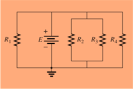
For each configuration of Fig. 6.65, �nd the voltage sources and for resistive elements (individual elements, not combinations of elements) that are in parallel.
Expert Solution & Answer

Trending nowThis is a popular solution!

Students have asked these similar questions
53. Obtain an expression for i(t) as labeled in the circuit diagram of Fig. 8.84, and
determine the power being dissipated in the 40 2 resistor at t = 2.5 ms.
t=0
i(t)
30 Ω
w
200 mA 4002
30 m
100 mA(
7.2
At t = 0, the switch in the circuit shown moves
instantaneously from position a to position b.
a) Calculate v, for t≥ 0.
b) What percentage of the initial energy stored
in the inductor is eventually dissipated in
the 4
resistor?
6Ω
a
w
+
10 0.32 H3 403
6.4 A
=0
b
Answer: (a) -8e-10 V, t = 0;
(b) 80%.
At t = 0, the switch closes. Find the IL(t) and VL(t) for t≥ 0 in t and s domain.
Can you help me?
1)
(+.
24V
ง
Anahtar t=0 anında kapatılıyor.
to icin TL(t) ve
bulunuz.
J
3√√√2
ww
مفروم
+
t=0
$6.5 5H VLCH) 2.2
Vilt)
Chapter 6 Solutions
Introductory Circuit Analysis (13th Edition)
Ch. 6 - For each configuration in Fig. 6.64, find the...Ch. 6 - For each configuration of Fig. 6.65, �nd the...Ch. 6 - For the network in Fig. 6.66: Find the elements...Ch. 6 - Find the total resistance for each configuration...Ch. 6 - Find the total resistance for each configuration...Ch. 6 - For each circuit board in Fig. 6.69, �nd the...Ch. 6 - The total resistance of each of the configurations...Ch. 6 - The total resistance for each configuration of...Ch. 6 - For the parallel network in Fig. 6.72, composed of...Ch. 6 - What is the ohmmeter reading for each...
Ch. 6 - Determine R1 for the network in Fig. 6.749.Ch. 6 - For the parallel network in Fig. 6.75: Find the...Ch. 6 - For the network of Fig. 6.76: Find the current...Ch. 6 - Repeat the analysis of Problem 13 for the network...Ch. 6 - For the parallel network in Fig. 6.78: Without...Ch. 6 - Given the information provided in Fig. 6.79, find:...Ch. 6 - Use the information in Fig. 6.80, to calculate:...Ch. 6 - Given the information provided in Fig. 6.81, find...Ch. 6 - For the network of Fig. 6.82, find: The voltage V....Ch. 6 - Using the information provided in Fig. 6.83 find:...Ch. 6 - For the network in Fig. 6.77: Redraw the network...Ch. 6 - For the configuration in Fig. 6.84: Find the total...Ch. 6 - Eight holiday lights are connected in parallel as...Ch. 6 - Determine the power delivered by the dc battery in...Ch. 6 - A portion of a residential service to a home is...Ch. 6 - For the network in Fig. 6.88: Find the current l1....Ch. 6 - Using Kirchhoffs current law, determine the...Ch. 6 - Using Kirchoffs current law, find the unknown...Ch. 6 - Using Kirchhoffs current law, determine the...Ch. 6 - Using the information provided in Fig. 6.92, find...Ch. 6 - Find the unknown quantities for the networks in...Ch. 6 - Find the unknown quantities for the networks of...Ch. 6 - Based solely on the resistor values, determine all...Ch. 6 - Determine one of the unknown currents of Fig....Ch. 6 - For each network of Fig. 6.97, determine the...Ch. 6 - Parts (a) through (e) of this problem should be...Ch. 6 - Find the unknown quantities for the networks in...Ch. 6 - Find resistance R for the network in Fig. 6.100...Ch. 6 - Design the network in Fig. 6.101 such that I2=2I1...Ch. 6 - Assuming identical supplies in Fig. 6.102: Find...Ch. 6 - Assuming identical supplies, determine currents...Ch. 6 - Assuming identical supplies, determine the current...Ch. 6 - For the simple series con�guration in Fig....Ch. 6 - Given the configuration in Fig. 6.106: What is the...Ch. 6 - Based on the measurements of Fig. 6.107, determine...Ch. 6 - Referring to Fig. 6.108, find the voltage Vab...Ch. 6 - The voltage Va for the network in Fig. 6.109, is...Ch. 6 - Prob. 48PCh. 6 - Using PSpice or Multisim, determine the solution...Ch. 6 - Using PSpice or Multisim, determine the solution...
Additional Engineering Textbook Solutions
Find more solutions based on key concepts
The Greatest and Least of These Write a program with a loop that lets the user enter a series of integers. The ...
Starting Out with C++ from Control Structures to Objects (9th Edition)
The rigid pipe is supported by a pin at A and an A-36 steel guy wire BD. If the wire has a diameter of 0.25 in....
Mechanics of Materials (10th Edition)
The priming read appears inside the validation loop.
Starting Out with Programming Logic and Design (5th Edition) (What's New in Computer Science)
The cable attach to the tractor at B exerts a force of 350 lb on the framework Express the force as a Cartesian...
INTERNATIONAL EDITION---Engineering Mechanics: Statics, 14th edition (SI unit)
Write a program to play the rock-paper-scissor game. Each of two users types in either P, R, or S. The program ...
Java: An Introduction to Problem Solving and Programming (8th Edition)
Distinguish among data definition commands, data manipulation commands, and data control commands.
Modern Database Management
Knowledge Booster


Learn more about
Need a deep-dive on the concept behind this application? Look no further. Learn more about this topic, electrical-engineering and related others by exploring similar questions and additional content below.Similar questions
- "For the network in the figure, determine RE and RB if A₁ Zb = BRE." = -10 and re = 3.8. Assume thatarrow_forward2.a. Simplify and determine Zk+ for: 2.x. 60 [Hz] ⚫ 2.y. 180 [Hz] a.x. 60[Hz] a.y. 180 [Hz] Joo (127 2[H] w 240 [√]arrow_forwardP3. Given the following network, determine: ⚫ 3.a. Equivalent Y ⚫ 3.b. Equivalent A 2 R[2] 10 8 b 20 30 5arrow_forward
- [Electrical Circuits] P1. Using the mesh current method, calculate the magnitude and direction of: 1.a. I and I (mesh currents) 1.b. I10 (test current in R10 = 1082) 1.c. (Calculate the magnitude and signs of V10) 6[A] 12 [√] بي 10 38 20 4A] Iw -800arrow_forwardNeed handwritten solution do not use chatgptarrow_forward[07/01, 16:59] C P: Question: Calculate the following for 100Hz and 500Hz (express all answers in phasor form). Show all work. A) Xc and ZTB) VR1 and VC1 C) IT Handwritten Solution Pleasearrow_forward
- 1. Sketch the root loci of a system with the following characteristic equation: s²+2s+2+K(s+2)=0 2. Sketch the root loci for the following loop transfer function: KG(s)H(s)=- K(s+1) s(s+2)(s²+2s+4)arrow_forward3. For the unity feedback system with forward path transfer function, G(s), below: G(s)= K(s² +8) (s+4)(s+5) Sketch the root locus and show the breakaway/break-in point(s) and jo-axis crossing. Determine the angle of arrival and K value at the breakaway/break- in point(s). Give your comment the system is stable or unstable.arrow_forwardFind the step response of each of the transfer functions shown in Eqs. (4.62) through (4.64) and compare them. [Shown in the image]Book: Norman S. Nise - Control Systems Engineering, 6th EditionTopic: Chapter-4: Time Response, Example 4.8Solve the math with proper explanation. Please don't give AI response. Asking for a expert verified answer.arrow_forward
- 2. With respect to the circuit shown in Figure 2 below V2 -R1 R2 R4 w R3 R5 Figure 2: DC Circuit 2 a. Using Ohm's and Kirchhoff's laws calculate the current flowing through R3 and so determine wattage rating of R3. b. Verify your results with simulations. Note: you must use the values for the components in Table 2. Table 2 V2 (Volts) R1 (KQ) R2 (KQ) R3 (KQ) R4 (KQ) R5 (KQ) 9 3.3 5 10 6 1 3.3arrow_forwardDon't use ai to answer i will report your answerarrow_forwardDon't use ai to answer I will report you answerarrow_forward
arrow_back_ios
SEE MORE QUESTIONS
arrow_forward_ios
Recommended textbooks for you
 Delmar's Standard Textbook Of ElectricityElectrical EngineeringISBN:9781337900348Author:Stephen L. HermanPublisher:Cengage Learning
 EBK ELECTRICAL WIRING RESIDENTIALElectrical EngineeringISBN:9781337516549Author:SimmonsPublisher:CENGAGE LEARNING - CONSIGNMENT
Delmar's Standard Textbook Of Electricity
Electrical Engineering
ISBN:9781337900348
Author:Stephen L. Herman
Publisher:Cengage Learning
EBK ELECTRICAL WIRING RESIDENTIAL
Electrical Engineering
ISBN:9781337516549
Author:Simmons
Publisher:CENGAGE LEARNING - CONSIGNMENT
Kirchhoff's Rules of Electrical Circuits; Author: Flipping Physics;https://www.youtube.com/watch?v=d0O-KUKP4nM;License: Standard YouTube License, CC-BY