
International Edition---engineering Mechanics: Statics, 4th Edition
4th Edition
ISBN: 9781305501607
Author: Andrew Pytel And Jaan Kiusalaas
Publisher: CENGAGE L
expand_more
expand_more
format_list_bulleted
Videos
Textbook Question
Chapter 6, Problem 6.7P
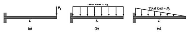
The three identical cantilever beams carry vertical loads that are distributed in a different manner. It is known that beam (a) fails because the maximum internal bending moment reaches its critical value when
Expert Solution & Answer
Want to see the full answer?
Check out a sample textbook solution
Students have asked these similar questions
Assume the B frame differs from the N frame through a 90 degree rotation about the second N base vector. The corresponding DCM description is:
1 2 3 4 5
6 9
# adjust the return matrix values as needed
def result():
dcm =
[0, 0, 0,
0, 0, 0,
0, 0, 0]
return dcm
Find the reaction at A and B
The other response I got was not too accurate,I need expert solved answer, don't use Artificial intelligence or screen shot it solving
No chatgpt pls
Chapter 6 Solutions
International Edition---engineering Mechanics: Statics, 4th Edition
Ch. 6 - Determine the internal force system acting on...Ch. 6 - Determine the internal force system acting on...Ch. 6 - Determine the internal force system acting on...Ch. 6 - Find the internal force systems acting on sections...Ch. 6 - Find the internal force systems acting on sections...Ch. 6 - Find the internal force systems acting on sections...Ch. 6 - The three identical cantilever beams carry...Ch. 6 - Determine the internal force systems acting on...Ch. 6 - For the structural component shown, determine the...Ch. 6 - Compute the internal force system acting on...
Ch. 6 - Determine the internal force system acting on...Ch. 6 - Determine the internal force systems acting on...Ch. 6 - Determine the internal force systems acting on...Ch. 6 - Find the internal force system acting on section 3...Ch. 6 - The structure is supported by a pin at C and a...Ch. 6 - The 1800lbin. couple is applied to member DEF of...Ch. 6 - A man of weight W climbs a ladder that has been...Ch. 6 - For the ladder in Prob. 6.17, find the internal...Ch. 6 - Determine the internal force system acting on...Ch. 6 - The equation of the parabolic arch is y=(36x2)/6,...Ch. 6 - For the beam shown, derive the expressions for V...Ch. 6 - For the beam shown, derive the expressions for V...Ch. 6 - For the beam shown, derive the expressions for V...Ch. 6 - For the beam shown, derive the expressions for V...Ch. 6 - For the beam shown, derive the expressions for V...Ch. 6 - For the beam shown, derive the expressions for V...Ch. 6 - For the beam shown, derive the expressions for V...Ch. 6 - For the beam shown, derive the expressions for V...Ch. 6 - For the beam shown, derive the expressions for V...Ch. 6 - For the beam shown, derive the expressions for V...Ch. 6 - For the beam shown, derive the expressions for V...Ch. 6 - For the beam shown, derive the expressions for V...Ch. 6 - For the beam shown, derive the expressions for V...Ch. 6 - For the beam shown, derive the expressions for V...Ch. 6 - For the beam shown, derive the expressions for V...Ch. 6 - For the beam shown, derive the expressions for V...Ch. 6 - For the beam shown, derive the expressions for V...Ch. 6 - For the beam shown, derive the expressions for V...Ch. 6 - Derive the shear force and the bending moment as...Ch. 6 - Derive the shear force and the bending moment as...Ch. 6 - The 24-ft timber floor joist is designed to carry...Ch. 6 - For the beam AB shown in Cases 1 and 2, derive and...Ch. 6 - Construct the shear force and bending moment...Ch. 6 - Construct the shear force and bending moment...Ch. 6 - Construct the shear force and bending moment...Ch. 6 - Construct the shear force and bending moment...Ch. 6 - Construct the shear force and bending moment...Ch. 6 - Construct the shear force and bending moment...Ch. 6 - Construct the shear force and bending moment...Ch. 6 - Construct the shear force and bending moment...Ch. 6 - Construct the shear force and bending moment...Ch. 6 - Construct the shear force and bending moment...Ch. 6 - Construct the shear force and bending moment...Ch. 6 - Construct the shear force and bending moment...Ch. 6 - Construct the shear force and bending moment...Ch. 6 - Construct the shear force and bending moment...Ch. 6 - Draw the load and the bending moment diagrams that...Ch. 6 - Draw the load and the bending moment diagrams that...Ch. 6 - Draw the load and the bending moment diagrams that...Ch. 6 - Draw the load and the bending moment diagrams that...Ch. 6 - Draw the load and the bending moment diagrams that...Ch. 6 - Show that the tension acting at a point in a...Ch. 6 - The cable of the suspension bridge spans L=140m...Ch. 6 - The two main cables of the Akashi Kaikyo...Ch. 6 - Cable AB supports the uniformly distributed load...Ch. 6 - A uniform 80-ft pipe that weighs 960 lb is...Ch. 6 - The cable AB supports a uniformly distributed load...Ch. 6 - The string attached to the kite weighs 0.4 oz/ft....Ch. 6 - Show that the tension acting at a point in a...Ch. 6 - A uniform cable weighing 16 N/m is suspended from...Ch. 6 - The tensions in the cable at points O and B are...Ch. 6 - The cable AOB weighs 24 N/m. Determine the sag H...Ch. 6 - The cable of mass 1.8 kg/m is attached to a rigid...Ch. 6 - One end of cable AB is fixed, whereas the other...Ch. 6 - The end of a water hose weighing 0.5 lb/ft is...Ch. 6 - The 50-ft measuring tape weighs 2.4 lb. Compute...Ch. 6 - The cable AOB weighs 5.2 N/m. When the horizontal...Ch. 6 - The chain OA is 25 ft long and weighs 5 lb/ft....Ch. 6 - The 110-lb traffic light is suspended from two...Ch. 6 - The cable carrying 60-lb loads at B and C is held...Ch. 6 - The cable ABCD is held in the position shown by...Ch. 6 - Find the forces in the three cable segments and...Ch. 6 - The cable carrying three 400-lb loads has a sag at...Ch. 6 - The cable supports three 400-lb loads as shown. If...Ch. 6 - Cable ABC of length 5 m supports the force W at B....Ch. 6 - When the 12-kN load and the unknown force P are...Ch. 6 - The cable is loaded by an 80-lb vertical force at...Ch. 6 - The 15-m-long cable supports the loads W1 and W2...Ch. 6 - The cable of length 15 m supports the forces...Ch. 6 - The 14-kN weight is suspended from a small pulley...Ch. 6 - For the cable ABCD determine (a) the angles 2 and...
Knowledge Booster


Learn more about
Need a deep-dive on the concept behind this application? Look no further. Learn more about this topic, mechanical-engineering and related others by exploring similar questions and additional content below.Similar questions
- Solve for the reaction of all the forces Don't use artificial intelligence or screen shot it, only expert should solvearrow_forwardNo chatgpt plsarrow_forwardA six cylinder petrol engine has a compression ratio of 5:1. The clearance volume of each cylinder is 110CC. It operates on the four-stroke constant volume cycle and the indicated efficiency ratio referred to air standard efficiency is 0.56. At the speed of 2400 rpm. 44000KJ/kg. Determine the consumes 10kg of fuel per hour. The calorific value of fuel average indicated mean effective pressure.arrow_forward
- The members of a truss are connected to the gusset plate as shown in (Figure 1). The forces are concurrent at point O. Take = 90° and T₁ = 7.5 kN. Part A Determine the magnitude of F for equilibrium. Express your answer to three significant figures and include the appropriate units. F= 7.03 Submit ? kN Previous Answers Request Answer × Incorrect; Try Again; 21 attempts remaining ▾ Part B Determine the magnitude of T2 for equilibrium. Express your answer to three significant figures and include the appropriate units. Figure T₂ = 7.03 C T2 |? KN Submit Previous Answers Request Answer × Incorrect; Try Again; 23 attempts remaining Provide Feedbackarrow_forwardConsider the following acid-base reaction: Fe3+(aq) +3H2O -Fe(OH)3 (s) + 3H* ← A. Using thermodynamics, calculate the equilibrium constant K at 25°C (The AG° of formation of Fe(OH)3(s) is -699 kJ/mol). B. Using the value of K you calculated in part a, if a solution contains 10-4 M Fe3+ and has a pH of 7.5, will Fe(OH)3(s) precipitate? Show all calculations necessary to justify your answer. Note that the reaction as written is for precipitation, not dissolution like Ksp-arrow_forwardA vertical force of F = 3.4 kN is applied to the hook at A as shown in. Set d = 1 m. Part A 3 m 3m 0.75 m 1.5 m. Determine the tension in cable AB for equilibrium. Express your answer to three significant figures and include the appropriate units. FAB= Value Submit Request Answer Part B Units ? Determine the tension in cable AC for equilibrium. Express your answer to three significant figures and include the appropriate units. FAC = Value Submit Request Answer Part C ? Units Determine the tension in cable AD for equilibrium. Express your answer to three significant figures and include the appropriate units.arrow_forward
- Consider the heat engine operating at steady state between the two thermal reservoirs shown at the right while producing a net power output of 700 kW. If 1000 kW of heat (Q̇H) is transferred to the heat engine from a thermal reservoir at a temperature of TH = 900 K, and heat is rejected to a thermal reservoir at a temperature of TL = 300 K, is this heat engine possible? Can you answer this question for me and show all of the workarrow_forward1.12 A disk of constant radius r is attached to a telescoping rod that is extending at a constant rate as shown in Fig. P1.12. Both the disk and the rod are rotating at a constant rate. Find the inertial velocity and acceleration of point P at the rim of the disk. ท2 L 0 SS P α e 0 O' êL Fig. P1.12 Rotating disk attached to telescoping rod. 60 LLarrow_forwardTwo different options A and B with brake pads for disc brakes are connected to the rope drum. The diameter of the rope drum is 150 mm. What distance must the pads B be at from the center of rotation to cover the same distance as A?A B- Width 50 mm - Width 60 mm- Evidence center 120mm - Construction power 900 N from rotation center.- Maintains a weight of 200 kgwhen the installation force is 1.4kN (μ is missing from the data)M=μF(Ry-Ri)Right answer R=187 mmarrow_forward
- Assume the xy plane is level ground, and that the vertical pole shown in the diagram lies along the z-axis with its base at the origin. If the pole is 5 m tall, and a rope is used to pull on the top of the pole with a force of 400 N as shown, determine the magnitudes of the parallel and perpendicular components of the force vector with respect to the axis of the post i.e. with respect to the z-axis.arrow_forward4-1 Q4: Q5: (20 Marks) Find √48 using False Position Method with three iterations. Hint: the root lies between 3 and 4. (20 Marks)arrow_forwardDetermine the angle between vectors FA and FB that is less than 180 degrees. FA is the vector drawn from the origin to point A (-4, 4, 2) while FB is the vector drawn from the origin to point B (3, 1, -3).arrow_forward
arrow_back_ios
SEE MORE QUESTIONS
arrow_forward_ios
Recommended textbooks for you
 Mechanics of Materials (MindTap Course List)Mechanical EngineeringISBN:9781337093347Author:Barry J. Goodno, James M. GerePublisher:Cengage Learning
Mechanics of Materials (MindTap Course List)
Mechanical Engineering
ISBN:9781337093347
Author:Barry J. Goodno, James M. Gere
Publisher:Cengage Learning
Mechanics of Materials Lecture: Beam Design; Author: UWMC Engineering;https://www.youtube.com/watch?v=-wVs5pvQPm4;License: Standard Youtube License