
International Edition---engineering Mechanics: Statics, 4th Edition
4th Edition
ISBN: 9781305501607
Author: Andrew Pytel And Jaan Kiusalaas
Publisher: CENGAGE L
expand_more
expand_more
format_list_bulleted
Concept explainers
Videos
Textbook Question
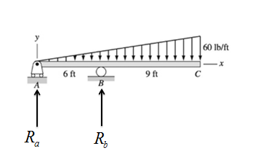
Chapter 6, Problem 6.38P
For the beam shown, derive the expressions for V and M, and draw the shear force and bending moment diagrams. Neglect the weight of the beam.
Expert Solution & Answer

Trending nowThis is a popular solution!

Students have asked these similar questions
oyfr
3. The figure shows a frame under the
influence of an external loading made up
of five forces and two moments. Use the
scalar method to calculate moments.
a. Write the resultant force of the
external loading in Cartesian vector
form.
b. Determine the
& direction
of the resultant moment of the
external loading about A.
15 cm
18 cm
2.2 N-m
B
50 N
45°
10 cm
48 N.m
250 N
60 N
20
21
50 N
25 cm
100 N
A
118,
27cm 5, 4:1
The 2-mass system shown below depicts a disk which rotates about its center and has rotational
moment of inertia Jo and radius r. The angular displacement of the disk is given by 0. The spring
with constant k₂ is attached to the disk at a distance from the center. The mass m has linear
displacement & and is subject to an external force u. When the system is at equilibrium, the spring
forces due to k₁ and k₂ are zero. Neglect gravity and aerodynamic drag in this problem. You may
assume the small angle approximation which implies (i) that the springs and dampers remain in
their horizontal / vertical configurations and (ii) that the linear displacement d of a point on the
edge of the disk can be approximated by d≈re.
Ө
K2
www
m
4
Cz
777777
Jo
Make the following assumptions when analyzing the forces and torques:
тв
2
0>0, 0>0, x> > 0, >0
Derive the differential equations of motion for this dynamic system. Start by sketching
LARGE and carefully drawn free-body-diagrams for the disk and the…
A linear system is one that satisfies the principle of superposition. In other words, if an input u₁
yields the output y₁, and an input u2 yields the output y2, the system is said to be linear if a com-
bination of the inputs u = u₁ + u2 yield the sum of the outputs y = y1 + y2.
Using this fact, determine the output y(t) of the following linear system:
given the input:
P(s) =
=
Y(s)
U(s)
=
s+1
s+10
u(t) = e−2+ sin(t)
=e
Chapter 6 Solutions
International Edition---engineering Mechanics: Statics, 4th Edition
Ch. 6 - Determine the internal force system acting on...Ch. 6 - Determine the internal force system acting on...Ch. 6 - Determine the internal force system acting on...Ch. 6 - Find the internal force systems acting on sections...Ch. 6 - Find the internal force systems acting on sections...Ch. 6 - Find the internal force systems acting on sections...Ch. 6 - The three identical cantilever beams carry...Ch. 6 - Determine the internal force systems acting on...Ch. 6 - For the structural component shown, determine the...Ch. 6 - Compute the internal force system acting on...
Ch. 6 - Determine the internal force system acting on...Ch. 6 - Determine the internal force systems acting on...Ch. 6 - Determine the internal force systems acting on...Ch. 6 - Find the internal force system acting on section 3...Ch. 6 - The structure is supported by a pin at C and a...Ch. 6 - The 1800lbin. couple is applied to member DEF of...Ch. 6 - A man of weight W climbs a ladder that has been...Ch. 6 - For the ladder in Prob. 6.17, find the internal...Ch. 6 - Determine the internal force system acting on...Ch. 6 - The equation of the parabolic arch is y=(36x2)/6,...Ch. 6 - For the beam shown, derive the expressions for V...Ch. 6 - For the beam shown, derive the expressions for V...Ch. 6 - For the beam shown, derive the expressions for V...Ch. 6 - For the beam shown, derive the expressions for V...Ch. 6 - For the beam shown, derive the expressions for V...Ch. 6 - For the beam shown, derive the expressions for V...Ch. 6 - For the beam shown, derive the expressions for V...Ch. 6 - For the beam shown, derive the expressions for V...Ch. 6 - For the beam shown, derive the expressions for V...Ch. 6 - For the beam shown, derive the expressions for V...Ch. 6 - For the beam shown, derive the expressions for V...Ch. 6 - For the beam shown, derive the expressions for V...Ch. 6 - For the beam shown, derive the expressions for V...Ch. 6 - For the beam shown, derive the expressions for V...Ch. 6 - For the beam shown, derive the expressions for V...Ch. 6 - For the beam shown, derive the expressions for V...Ch. 6 - For the beam shown, derive the expressions for V...Ch. 6 - For the beam shown, derive the expressions for V...Ch. 6 - Derive the shear force and the bending moment as...Ch. 6 - Derive the shear force and the bending moment as...Ch. 6 - The 24-ft timber floor joist is designed to carry...Ch. 6 - For the beam AB shown in Cases 1 and 2, derive and...Ch. 6 - Construct the shear force and bending moment...Ch. 6 - Construct the shear force and bending moment...Ch. 6 - Construct the shear force and bending moment...Ch. 6 - Construct the shear force and bending moment...Ch. 6 - Construct the shear force and bending moment...Ch. 6 - Construct the shear force and bending moment...Ch. 6 - Construct the shear force and bending moment...Ch. 6 - Construct the shear force and bending moment...Ch. 6 - Construct the shear force and bending moment...Ch. 6 - Construct the shear force and bending moment...Ch. 6 - Construct the shear force and bending moment...Ch. 6 - Construct the shear force and bending moment...Ch. 6 - Construct the shear force and bending moment...Ch. 6 - Construct the shear force and bending moment...Ch. 6 - Draw the load and the bending moment diagrams that...Ch. 6 - Draw the load and the bending moment diagrams that...Ch. 6 - Draw the load and the bending moment diagrams that...Ch. 6 - Draw the load and the bending moment diagrams that...Ch. 6 - Draw the load and the bending moment diagrams that...Ch. 6 - Show that the tension acting at a point in a...Ch. 6 - The cable of the suspension bridge spans L=140m...Ch. 6 - The two main cables of the Akashi Kaikyo...Ch. 6 - Cable AB supports the uniformly distributed load...Ch. 6 - A uniform 80-ft pipe that weighs 960 lb is...Ch. 6 - The cable AB supports a uniformly distributed load...Ch. 6 - The string attached to the kite weighs 0.4 oz/ft....Ch. 6 - Show that the tension acting at a point in a...Ch. 6 - A uniform cable weighing 16 N/m is suspended from...Ch. 6 - The tensions in the cable at points O and B are...Ch. 6 - The cable AOB weighs 24 N/m. Determine the sag H...Ch. 6 - The cable of mass 1.8 kg/m is attached to a rigid...Ch. 6 - One end of cable AB is fixed, whereas the other...Ch. 6 - The end of a water hose weighing 0.5 lb/ft is...Ch. 6 - The 50-ft measuring tape weighs 2.4 lb. Compute...Ch. 6 - The cable AOB weighs 5.2 N/m. When the horizontal...Ch. 6 - The chain OA is 25 ft long and weighs 5 lb/ft....Ch. 6 - The 110-lb traffic light is suspended from two...Ch. 6 - The cable carrying 60-lb loads at B and C is held...Ch. 6 - The cable ABCD is held in the position shown by...Ch. 6 - Find the forces in the three cable segments and...Ch. 6 - The cable carrying three 400-lb loads has a sag at...Ch. 6 - The cable supports three 400-lb loads as shown. If...Ch. 6 - Cable ABC of length 5 m supports the force W at B....Ch. 6 - When the 12-kN load and the unknown force P are...Ch. 6 - The cable is loaded by an 80-lb vertical force at...Ch. 6 - The 15-m-long cable supports the loads W1 and W2...Ch. 6 - The cable of length 15 m supports the forces...Ch. 6 - The 14-kN weight is suspended from a small pulley...Ch. 6 - For the cable ABCD determine (a) the angles 2 and...
Knowledge Booster


Learn more about
Need a deep-dive on the concept behind this application? Look no further. Learn more about this topic, mechanical-engineering and related others by exploring similar questions and additional content below.Similar questions
- The manometer fluid in the figure given below is mercury where D = 3 in and h = 1 in. Estimate the volume flow in the tube (ft3/s) if the flowing fluid is gasoline at 20°C and 1 atm. The density of mercury and gasoline are 26.34 slug/ft3 and 1.32 slug/ft3 respectively. The gravitational force is 32.2 ft/s2.arrow_forwardUsing the Bernoulli equation to find the general solution. If an initial condition is given, find the particular solution. y' + xy = xy¯¹, y(0) = 3arrow_forwardTest for exactness. If exact, solve. If not, use an integrating factor as given or obtained by inspection or by the theorems in the text. a. 2xydx+x²dy = 0 b. (x2+y2)dx-2xydy = 0 c. 6xydx+5(y + x2)dy = 0arrow_forward
- Newton's law of cooling. A thermometer, reading 5°C, is brought into a room whose temperature is 22°C. One minute later the thermometer reading is 12°C. How long does it take until the reading is practically 22°C, say, 21.9°C?arrow_forwardSolve a. y' + 2xy = ex-x² b. y' + y sin x = ecosx, y(0) = −1 y(0) = −2.5arrow_forward= MMB 241 Tutorial 3.pdf 2/6 90% + + 5. The boat is traveling along the circular path with a speed of v = (0.0625t²) m/s, where t is in seconds. Determine the magnitude of its acceleration when t = 10 s. 40 m v = 0.0625² 6. If the motorcycle has a deceleration of at = (0.001s) m/s² and its speed at position A is 25 m/s, determine the magnitude of its acceleration when it passes point B. .A 90° 300 m n B 2arrow_forward
- = MMB 241 Tutorial 3.pdf 4/6 67% + 9. The car is traveling along the road with a speed of v = (2 s) m/s, where s is in meters. Determine the magnitude of its acceleration when s = 10 m. v = (2s) m/s 50 m 10. The platform is rotating about the vertical axis such that at any instant its angular position is u = (4t 3/2) rad, where t is in seconds. A ball rolls outward along the radial groove so that its position is r = (0.1+³) m, where t is in seconds. Determine the magnitudes of the velocity and acceleration of the ball when t = 1.5s.arrow_forwardThe population of a certain country is known to increase at a rate proportional to the number of people presently living in the country. If after two years the population has doubled, and after three years the population is 20,000, estimate the number of people initially living in the country.arrow_forward= MMB 241 Tutorial 3.pdf 6/6 100% + | 日 13. The slotted link is pinned at O, and as a result of the constant angular velocity *= 3 rad/s it drives the peg P for a short distance along the spiral guide r = (0.40) m, where 0 is in radians. Determine the radial and transverse components of the velocity and acceleration of P at the instant = 1/3 rad. 0.5 m P r = 0.40 =3 rad/sarrow_forward
- = MMB 241 Tutorial 3.pdf 1/6 90% + DYNAMICS OF PARTICLES (MMB 241) Tutorial 3 Topic: Kinematics of Particles:- Path and Polar coordinate systems and general curvilinear QUESTIONS motion. 1. Determine the acceleration at s = 2 m if v = (2 s) m/s², where s is in meters. At s = 0, v = 1 m/s. 3 m 2. Determine the acceleration when t=1s if v = (4t2+2) m/s, where t is in seconds. v=(4²+2) m/s 6 marrow_forward5.112 A mounting bracket for electronic components is formed from sheet metal with a uniform thickness. Locate the center of gravity of the bracket. 0.75 in. 3 in. ༧ Fig. P5.112 1.25 in. 0.75 in. y r = 0.625 in. 2.5 in. 1 in. 6 in. xarrow_forward4-105. Replace the force system acting on the beam by an equivalent resultant force and couple moment at point B. A 30 in. 4 in. 12 in. 16 in. B 30% 3 in. 10 in. 250 lb 260 lb 13 5 12 300 lbarrow_forward
arrow_back_ios
SEE MORE QUESTIONS
arrow_forward_ios
Recommended textbooks for you
 International Edition---engineering Mechanics: St...Mechanical EngineeringISBN:9781305501607Author:Andrew Pytel And Jaan KiusalaasPublisher:CENGAGE L
International Edition---engineering Mechanics: St...
Mechanical Engineering
ISBN:9781305501607
Author:Andrew Pytel And Jaan Kiusalaas
Publisher:CENGAGE L
Understanding Shear Force and Bending Moment Diagrams; Author: The Efficient Engineer;https://www.youtube.com/watch?v=C-FEVzI8oe8;License: Standard YouTube License, CC-BY
Bending Stress; Author: moodlemech;https://www.youtube.com/watch?v=9QIqewkE6xM;License: Standard Youtube License