
International Edition---engineering Mechanics: Statics, 4th Edition
4th Edition
ISBN: 9781305501607
Author: Andrew Pytel And Jaan Kiusalaas
Publisher: CENGAGE L
expand_more
expand_more
format_list_bulleted
Concept explainers
Videos
Textbook Question
Chapter 6, Problem 6.66P
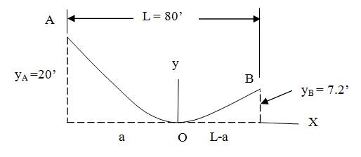
A uniform 80-ft pipe that weighs 960 lb is supported entirely by a cable AB of negligible weight. Determine the length of the cable and the maximum force in the cable. (Hint: First locate the point O where the cable is tangent to the pipe.)
Expert Solution & Answer

Trending nowThis is a popular solution!

Students have asked these similar questions
Qu 5 Determine the carburizing time necessary to achieve a carbon concentration of 0.30 wt% at a position 4 mm into an iron carbon alloy that initially contains 0.10 wt% C. The surface concentration is to be maintained at 0.90 wt% C, and the treatment is to be conducted at 1100°C. Use the data for the diffusion of
carbon into y-iron: Do = 2.3 x10⁻⁵ m2/s and Qd = 148,000 J/mol. Express your answer in hours to three significant figures.
show all work step by step problems formula material science
(Read Question)
In figure A, the homogeneous rod of constant cross section is attached to unyielding supports. In figure B, a homogeneous bar with a cross-sectional area of 600 mm2 is attached to rigid supports. The bar carries the axial loads P1 = 20 kN and P2 = 60 kN, as shown.1. In figure A, derive the expression that calculates the reaction R1 in terms of P, and the given dimensions.2. In figure B, calculate the reaction (kN) at A.3. In figure B, calculate the maximum axial stress (MPa) in the rod.
Chapter 6 Solutions
International Edition---engineering Mechanics: Statics, 4th Edition
Ch. 6 - Determine the internal force system acting on...Ch. 6 - Determine the internal force system acting on...Ch. 6 - Determine the internal force system acting on...Ch. 6 - Find the internal force systems acting on sections...Ch. 6 - Find the internal force systems acting on sections...Ch. 6 - Find the internal force systems acting on sections...Ch. 6 - The three identical cantilever beams carry...Ch. 6 - Determine the internal force systems acting on...Ch. 6 - For the structural component shown, determine the...Ch. 6 - Compute the internal force system acting on...
Ch. 6 - Determine the internal force system acting on...Ch. 6 - Determine the internal force systems acting on...Ch. 6 - Determine the internal force systems acting on...Ch. 6 - Find the internal force system acting on section 3...Ch. 6 - The structure is supported by a pin at C and a...Ch. 6 - The 1800lbin. couple is applied to member DEF of...Ch. 6 - A man of weight W climbs a ladder that has been...Ch. 6 - For the ladder in Prob. 6.17, find the internal...Ch. 6 - Determine the internal force system acting on...Ch. 6 - The equation of the parabolic arch is y=(36x2)/6,...Ch. 6 - For the beam shown, derive the expressions for V...Ch. 6 - For the beam shown, derive the expressions for V...Ch. 6 - For the beam shown, derive the expressions for V...Ch. 6 - For the beam shown, derive the expressions for V...Ch. 6 - For the beam shown, derive the expressions for V...Ch. 6 - For the beam shown, derive the expressions for V...Ch. 6 - For the beam shown, derive the expressions for V...Ch. 6 - For the beam shown, derive the expressions for V...Ch. 6 - For the beam shown, derive the expressions for V...Ch. 6 - For the beam shown, derive the expressions for V...Ch. 6 - For the beam shown, derive the expressions for V...Ch. 6 - For the beam shown, derive the expressions for V...Ch. 6 - For the beam shown, derive the expressions for V...Ch. 6 - For the beam shown, derive the expressions for V...Ch. 6 - For the beam shown, derive the expressions for V...Ch. 6 - For the beam shown, derive the expressions for V...Ch. 6 - For the beam shown, derive the expressions for V...Ch. 6 - For the beam shown, derive the expressions for V...Ch. 6 - Derive the shear force and the bending moment as...Ch. 6 - Derive the shear force and the bending moment as...Ch. 6 - The 24-ft timber floor joist is designed to carry...Ch. 6 - For the beam AB shown in Cases 1 and 2, derive and...Ch. 6 - Construct the shear force and bending moment...Ch. 6 - Construct the shear force and bending moment...Ch. 6 - Construct the shear force and bending moment...Ch. 6 - Construct the shear force and bending moment...Ch. 6 - Construct the shear force and bending moment...Ch. 6 - Construct the shear force and bending moment...Ch. 6 - Construct the shear force and bending moment...Ch. 6 - Construct the shear force and bending moment...Ch. 6 - Construct the shear force and bending moment...Ch. 6 - Construct the shear force and bending moment...Ch. 6 - Construct the shear force and bending moment...Ch. 6 - Construct the shear force and bending moment...Ch. 6 - Construct the shear force and bending moment...Ch. 6 - Construct the shear force and bending moment...Ch. 6 - Draw the load and the bending moment diagrams that...Ch. 6 - Draw the load and the bending moment diagrams that...Ch. 6 - Draw the load and the bending moment diagrams that...Ch. 6 - Draw the load and the bending moment diagrams that...Ch. 6 - Draw the load and the bending moment diagrams that...Ch. 6 - Show that the tension acting at a point in a...Ch. 6 - The cable of the suspension bridge spans L=140m...Ch. 6 - The two main cables of the Akashi Kaikyo...Ch. 6 - Cable AB supports the uniformly distributed load...Ch. 6 - A uniform 80-ft pipe that weighs 960 lb is...Ch. 6 - The cable AB supports a uniformly distributed load...Ch. 6 - The string attached to the kite weighs 0.4 oz/ft....Ch. 6 - Show that the tension acting at a point in a...Ch. 6 - A uniform cable weighing 16 N/m is suspended from...Ch. 6 - The tensions in the cable at points O and B are...Ch. 6 - The cable AOB weighs 24 N/m. Determine the sag H...Ch. 6 - The cable of mass 1.8 kg/m is attached to a rigid...Ch. 6 - One end of cable AB is fixed, whereas the other...Ch. 6 - The end of a water hose weighing 0.5 lb/ft is...Ch. 6 - The 50-ft measuring tape weighs 2.4 lb. Compute...Ch. 6 - The cable AOB weighs 5.2 N/m. When the horizontal...Ch. 6 - The chain OA is 25 ft long and weighs 5 lb/ft....Ch. 6 - The 110-lb traffic light is suspended from two...Ch. 6 - The cable carrying 60-lb loads at B and C is held...Ch. 6 - The cable ABCD is held in the position shown by...Ch. 6 - Find the forces in the three cable segments and...Ch. 6 - The cable carrying three 400-lb loads has a sag at...Ch. 6 - The cable supports three 400-lb loads as shown. If...Ch. 6 - Cable ABC of length 5 m supports the force W at B....Ch. 6 - When the 12-kN load and the unknown force P are...Ch. 6 - The cable is loaded by an 80-lb vertical force at...Ch. 6 - The 15-m-long cable supports the loads W1 and W2...Ch. 6 - The cable of length 15 m supports the forces...Ch. 6 - The 14-kN weight is suspended from a small pulley...Ch. 6 - For the cable ABCD determine (a) the angles 2 and...
Knowledge Booster


Learn more about
Need a deep-dive on the concept behind this application? Look no further. Learn more about this topic, mechanical-engineering and related others by exploring similar questions and additional content below.Similar questions
- (Read image)arrow_forward(Read Image)arrow_forwardM16x2 grade 8.8 bolts No. 25 C1- Q.2. The figure is a cross section of a grade 25 cast-iron pressure vessel. A total of N, M16x2.0 grade 8.8 bolts are to be used to resist a separating force of 160 kN. (a) Determine ks, km, and C. (b) Find the number of bolts required for a load factor of 2 where the bolts may be reused when the joint 19 mm is taken apart. (c) with the number of bolts obtained in (b), determine the realized load factor for overload, the yielding factor of safety, and the separation factor of safety. 19 mmarrow_forward
- Problem4. The thin uniform disk of mass m = 1-kg and radius R = 0.1m spins about the bent shaft OG with the angular speed w2 = 20 rad/s. At the same time, the shaft rotates about the z-axis with the angular speed 001 = 10 rad/s. The angle between the bent portion of the shaft and the z-axis is ẞ = 35°. The mass of the shaft is negligible compared to the mass of the disk. a. Find the angular momentum of the disk with respect to point G, based on the axis orientation as shown. Include an MVD in your solution. b. Find the angular momentum of the disk with respect to point O, based on the axis orientation as shown. (Note: O is NOT the center of fixed-point rotation.) c. Find the kinetic energy of the assembly. z R R 002 2R x Answer: H = -0.046ĵ-0.040 kg-m²/sec Ho=-0.146-0.015 kg-m²/sec T 0.518 N-m =arrow_forwardProblem 3. The assembly shown consists of a solid sphere of mass m and the uniform slender rod of the same mass, both of which are welded to the shaft. The assembly is rotating with angular velocity w at a particular moment. Find the angular momentum with respect to point O, in terms of the axes shown. Answer: Ñ。 = ½mc²wcosßsinßĵ + (}{mr²w + 2mb²w + ½ mc²wcos²ß) k 3 m r b 2 C لا marrow_forwardOnly question 2arrow_forward
- Only question 1arrow_forwardOnly question 3arrow_forwardI have Euler parameters that describe the orientation of N relative to Q, e = -0.7071*n3, e4 = 0.7071. I have Euler parameters that describe the orientation of U relative to N, e = -1/sqrt(3)*n1, e4 = sqrt(2/3). After using euler parameter rule of successive rotations, I get euler parameters that describe the orientation of U relative to Q, e = -0.4082*n1 - 0.4082*n2 - 0.5774*n3. I need euler parameters that describe the orientation of U relative to Q in vector basis of q instead of n. How do I get that?arrow_forward
- Describe at least 4 processes in engineering where control charts are (or should be) appliedarrow_forwardDescribe at least two (2) processes where control charts are (or should be) applied.arrow_forwardProblem 3: A cube-shaped spacecraft is in a circular Earth orbit. Let N (n,) be inertial and the spacecraft is denoted S (ŝ₁). The spacecraft is described such that ¯½º = J ŝ₁ŝ₁ + J ŝ₂§₂ + J §¸Ŝ3 Location of the spacecraft in the orbit is determined by the orbit-fixed unit vectors ê, that are oriented by the angle (Qt), where is a constant angular rate. 52 €3 3> 2t 55 Λ Из At the instant when Qt = 90°, the spacecraft S is oriented relative to the orbit such that 8₁ = 0° Space-three 1-2-3 angles 0₂ = 60° and ES = $₂ rad/s 0₁ = 135° (a) At this instant, determine the direction cosine matrix that describes the orientation of the spacecraft with respect to the inertial frame N.arrow_forward
arrow_back_ios
SEE MORE QUESTIONS
arrow_forward_ios
Recommended textbooks for you
 International Edition---engineering Mechanics: St...Mechanical EngineeringISBN:9781305501607Author:Andrew Pytel And Jaan KiusalaasPublisher:CENGAGE L
International Edition---engineering Mechanics: St...
Mechanical Engineering
ISBN:9781305501607
Author:Andrew Pytel And Jaan Kiusalaas
Publisher:CENGAGE L
Engineering Basics - Statics & Forces in Equilibrium; Author: Solid Solutions - Professional Design Solutions;https://www.youtube.com/watch?v=dQBvQ2hJZFg;License: Standard YouTube License, CC-BY