
International Edition---engineering Mechanics: Statics, 4th Edition
4th Edition
ISBN: 9781305501607
Author: Andrew Pytel And Jaan Kiusalaas
Publisher: CENGAGE L
expand_more
expand_more
format_list_bulleted
Concept explainers
Videos
Textbook Question
Chapter 6, Problem 6.32P
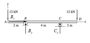
For the beam shown, derive the expressions for V and M, and draw the shear force and bending moment diagrams. Neglect the weight of the beam.
Expert Solution & Answer
Want to see the full answer?
Check out a sample textbook solution
Students have asked these similar questions
Please only step 6 (last time I asked it was cut off at that point)
Please Please use a MATLAB with codes and grap. Recreate the following four Figures of the textbook using MATLAB and the appropriate parameters. Comment on your observations for each Figure. List all of the parameters that you have used. The figure attached below.
I REPEAT!!!!! I NEED HANDDRAWING!!!!! NOT A USELESS EXPLANATION!!!! I REPEAT SUBMIT A HANDDRAWING IF YOU CANNOT UNDERSTAND THIS SKIP IT !
I need the real handdrawing complete it by adding these :
Pneumatic Valves
Each linear actuator must be controlled by a directional control valve (DCV) (e.g., 5/2 or 4/2 valve).
The bi-directional motor requires a reversible valve to change rotation direction.
Pressure Regulators & Air Supply
Include two pressure regulators as per the assignment requirement.
Show the main compressed air supply line connecting all components.
Limit Switches & Safety Features
Attach limit switches to each actuator to detect positions.
Implement a two-handed push-button safety system to control actuator movement.
Connections Between Components
Draw air supply lines linking the compressor, valves, and actuators.
Clearly label all inputs and outputs for better understanding.
Chapter 6 Solutions
International Edition---engineering Mechanics: Statics, 4th Edition
Ch. 6 - Determine the internal force system acting on...Ch. 6 - Determine the internal force system acting on...Ch. 6 - Determine the internal force system acting on...Ch. 6 - Find the internal force systems acting on sections...Ch. 6 - Find the internal force systems acting on sections...Ch. 6 - Find the internal force systems acting on sections...Ch. 6 - The three identical cantilever beams carry...Ch. 6 - Determine the internal force systems acting on...Ch. 6 - For the structural component shown, determine the...Ch. 6 - Compute the internal force system acting on...
Ch. 6 - Determine the internal force system acting on...Ch. 6 - Determine the internal force systems acting on...Ch. 6 - Determine the internal force systems acting on...Ch. 6 - Find the internal force system acting on section 3...Ch. 6 - The structure is supported by a pin at C and a...Ch. 6 - The 1800lbin. couple is applied to member DEF of...Ch. 6 - A man of weight W climbs a ladder that has been...Ch. 6 - For the ladder in Prob. 6.17, find the internal...Ch. 6 - Determine the internal force system acting on...Ch. 6 - The equation of the parabolic arch is y=(36x2)/6,...Ch. 6 - For the beam shown, derive the expressions for V...Ch. 6 - For the beam shown, derive the expressions for V...Ch. 6 - For the beam shown, derive the expressions for V...Ch. 6 - For the beam shown, derive the expressions for V...Ch. 6 - For the beam shown, derive the expressions for V...Ch. 6 - For the beam shown, derive the expressions for V...Ch. 6 - For the beam shown, derive the expressions for V...Ch. 6 - For the beam shown, derive the expressions for V...Ch. 6 - For the beam shown, derive the expressions for V...Ch. 6 - For the beam shown, derive the expressions for V...Ch. 6 - For the beam shown, derive the expressions for V...Ch. 6 - For the beam shown, derive the expressions for V...Ch. 6 - For the beam shown, derive the expressions for V...Ch. 6 - For the beam shown, derive the expressions for V...Ch. 6 - For the beam shown, derive the expressions for V...Ch. 6 - For the beam shown, derive the expressions for V...Ch. 6 - For the beam shown, derive the expressions for V...Ch. 6 - For the beam shown, derive the expressions for V...Ch. 6 - Derive the shear force and the bending moment as...Ch. 6 - Derive the shear force and the bending moment as...Ch. 6 - The 24-ft timber floor joist is designed to carry...Ch. 6 - For the beam AB shown in Cases 1 and 2, derive and...Ch. 6 - Construct the shear force and bending moment...Ch. 6 - Construct the shear force and bending moment...Ch. 6 - Construct the shear force and bending moment...Ch. 6 - Construct the shear force and bending moment...Ch. 6 - Construct the shear force and bending moment...Ch. 6 - Construct the shear force and bending moment...Ch. 6 - Construct the shear force and bending moment...Ch. 6 - Construct the shear force and bending moment...Ch. 6 - Construct the shear force and bending moment...Ch. 6 - Construct the shear force and bending moment...Ch. 6 - Construct the shear force and bending moment...Ch. 6 - Construct the shear force and bending moment...Ch. 6 - Construct the shear force and bending moment...Ch. 6 - Construct the shear force and bending moment...Ch. 6 - Draw the load and the bending moment diagrams that...Ch. 6 - Draw the load and the bending moment diagrams that...Ch. 6 - Draw the load and the bending moment diagrams that...Ch. 6 - Draw the load and the bending moment diagrams that...Ch. 6 - Draw the load and the bending moment diagrams that...Ch. 6 - Show that the tension acting at a point in a...Ch. 6 - The cable of the suspension bridge spans L=140m...Ch. 6 - The two main cables of the Akashi Kaikyo...Ch. 6 - Cable AB supports the uniformly distributed load...Ch. 6 - A uniform 80-ft pipe that weighs 960 lb is...Ch. 6 - The cable AB supports a uniformly distributed load...Ch. 6 - The string attached to the kite weighs 0.4 oz/ft....Ch. 6 - Show that the tension acting at a point in a...Ch. 6 - A uniform cable weighing 16 N/m is suspended from...Ch. 6 - The tensions in the cable at points O and B are...Ch. 6 - The cable AOB weighs 24 N/m. Determine the sag H...Ch. 6 - The cable of mass 1.8 kg/m is attached to a rigid...Ch. 6 - One end of cable AB is fixed, whereas the other...Ch. 6 - The end of a water hose weighing 0.5 lb/ft is...Ch. 6 - The 50-ft measuring tape weighs 2.4 lb. Compute...Ch. 6 - The cable AOB weighs 5.2 N/m. When the horizontal...Ch. 6 - The chain OA is 25 ft long and weighs 5 lb/ft....Ch. 6 - The 110-lb traffic light is suspended from two...Ch. 6 - The cable carrying 60-lb loads at B and C is held...Ch. 6 - The cable ABCD is held in the position shown by...Ch. 6 - Find the forces in the three cable segments and...Ch. 6 - The cable carrying three 400-lb loads has a sag at...Ch. 6 - The cable supports three 400-lb loads as shown. If...Ch. 6 - Cable ABC of length 5 m supports the force W at B....Ch. 6 - When the 12-kN load and the unknown force P are...Ch. 6 - The cable is loaded by an 80-lb vertical force at...Ch. 6 - The 15-m-long cable supports the loads W1 and W2...Ch. 6 - The cable of length 15 m supports the forces...Ch. 6 - The 14-kN weight is suspended from a small pulley...Ch. 6 - For the cable ABCD determine (a) the angles 2 and...
Knowledge Booster


Learn more about
Need a deep-dive on the concept behind this application? Look no further. Learn more about this topic, mechanical-engineering and related others by exploring similar questions and additional content below.Similar questions
- I need the real handdrawing complete it by adding these : Pneumatic Valves Each linear actuator must be controlled by a directional control valve (DCV) (e.g., 5/2 or 4/2 valve). The bi-directional motor requires a reversible valve to change rotation direction. Pressure Regulators & Air Supply Include two pressure regulators as per the assignment requirement. Show the main compressed air supply line connecting all components. Limit Switches & Safety Features Attach limit switches to each actuator to detect positions. Implement a two-handed push-button safety system to control actuator movement. Connections Between Components Draw air supply lines linking the compressor, valves, and actuators. Clearly label all inputs and outputs for better understanding.arrow_forwardAn elastic bar of the length L and cross section area A is rigidly attached to the ceiling of a room, and it supports a mass M. Due to the acceleration of gravity g the rod deforms vertically. The deformation of the rod is measured by the vertical displacement u(x) governed by the following equations: dx (σ(x)) + b(x) = 0 PDE σ(x) = Edx du Hooke's law (1) b(x) = gp= body force per unit volume where E is the constant Young's modulus, p is the density, and σ(x) the axial stress in the rod. g * I u(x) L 2arrow_forwardAn elastic bar of the length L and cross section area A is rigidly attached to the ceiling of a room, and it supports a mass M. Due to the acceleration of gravity g the rod deforms vertically. The deformation of the rod is measured by the vertical displacement u(x) governed by the following equations: dx (σ(x)) + b(x) = 0 PDE σ(x) = Edx du Hooke's law (1) b(x) = gp= body force per unit volume where E is the constant Young's modulus, p is the density, and σ(x) the axial stress in the rod. g * I u(x) L 2arrow_forward
- متوسعة الفرج بو عمامة المستوى رم الواجب المنزلي رقم 04 تمرین الوان حسب يتمعن العبارات الأتية : A= (+2)+(-45) B=(+13)- C = (+17)-(+13)-(-20)+(-19 D= [(-15)-(+15)]-[(+20) + هست قیم مدرج مبدؤه النقطة ة الطول :tcm A(-2,5): B(+ 2,5) ≤ C (+5) المسافتين : BAD ين الثاني لمستوي مبدؤه 8 وحدتهarrow_forwardPlease do not rely too much on AI, because its answer may be wrong. Please consider it carefully and give your own answer!!!!! You can borrow ideas from AI, but please do not believe its answer.Very very grateful! ( If you write by hand or don't use AI, I'll give you a big thumbs up ) Please do not copy other's work,i will be very very grateful!!Please do not copy other's work,i will be very very grateful!!arrow_forwardA thin uniform rod of mass m and length 2r rests in a smooth hemispherical bowl of radius r. A moment M = mgr horizontal plane. is applied to the rod. Assume that the bowl is fixed and its rim is in the HINT: It will help you to find the length l of that portion of the rod that remains outside the bowl. M 2r Ꮎ a) How many degrees of freedom does this system have? b) Write an equation for the virtual work in terms of the angle 0 and the motion of the center of mass (TF) c) Derive an equation for the variation in the position of the center of mass (i.e., Sŕƒ) a. HINT: Use the center of the bowl as the coordinate system origin for the problem. d) In the case of no applied moment (i.e., M = 0), derive an equation that can be used to solve for the equilibrium angle of the rod. DO NOT solve the equation e) In the case of an applied moment (i.e., M: = mgr 4 -) derive an equation that can be used to solve for the equilibrium angle of the rod. DO NOT solve the equation. f) Can the angle 0 and…arrow_forward
- Please do not rely too much on chatgpt, because its answer may be wrong. Please consider it carefully and give your own answer. You can borrow ideas from gpt, but please do not believe its answer.Very very grateful! Please do not copy other's work,i will be very very grateful!!Please do not copy other's work,i will be very very grateful!!arrow_forward= The frame shown is fitted with three 50 cm diameter frictionless pulleys. A force of F = 630 N is applied to the rope at an angle ◊ 43°. Member ABCD is attached to the wall by a fixed support at A. Find the forces indicated below. Note: The rope is tangent to the pully (D) and not secured at the 3 o'clock position. a b •C *су G E e d BY NC SA 2013 Michael Swanbom Values for dimensions on the figure are given in the following table. Note the figure may not be to scale. Variable Value a 81 cm b 50 cm с 59 cm d 155 cm For all answers, take x as positive to the right and positive upward. At point A, the fixed support exerts a force of: A = + ĴN and a reaction couple of: →> ΜΑ Member CG is in Select an answer magnitude У as k N-m. and carries a force of N.arrow_forwardThe lower jaw AB [Purple 1] and the upper jaw-handle AD [Yellow 2] exert vertical clamping forces on the object at R. The hand squeezes the upper jaw-handle AD [2] and the lower handle BC [Orane 4] with forces F. (Member CD [Red 3] acts as if it is pinned at D, but, in a real vise-grips, its position is actually adjustable.) The clamping force, R, depends on the geometry and on the squeezing force F applied to the handles. Determine the proportionality between the clamping force, R, and the squeezing force F for the dimensions given. d3 d4 R 1 B d1 2 d2 D... d5 F 4 F Values for dimensions on the figure are given in the following table. Note the figure may not be to scale. Variable Value d1 65 mm d2 156 mm d3 50 mm 45 d4 d5 113 mm 30 mm R = Farrow_forward
arrow_back_ios
SEE MORE QUESTIONS
arrow_forward_ios
Recommended textbooks for you
 International Edition---engineering Mechanics: St...Mechanical EngineeringISBN:9781305501607Author:Andrew Pytel And Jaan KiusalaasPublisher:CENGAGE L
International Edition---engineering Mechanics: St...
Mechanical Engineering
ISBN:9781305501607
Author:Andrew Pytel And Jaan Kiusalaas
Publisher:CENGAGE L
Understanding Shear Force and Bending Moment Diagrams; Author: The Efficient Engineer;https://www.youtube.com/watch?v=C-FEVzI8oe8;License: Standard YouTube License, CC-BY
Bending Stress; Author: moodlemech;https://www.youtube.com/watch?v=9QIqewkE6xM;License: Standard Youtube License