
International Edition---engineering Mechanics: Statics, 4th Edition
4th Edition
ISBN: 9781305501607
Author: Andrew Pytel And Jaan Kiusalaas
Publisher: CENGAGE L
expand_more
expand_more
format_list_bulleted
Concept explainers
Videos
Textbook Question
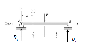
Chapter 6, Problem 6.42P
For the beam AB shown in Cases 1 and 2, derive and plot expressions for the shear force and bending moment acting on section 1 in terms of the distance x (0 < x< L). [Note: Case 1 results in the conventional V- and M-diagrams, in which the loads are fixed and the location of the section varies; the diagrams for Case 2 (called influence diagrams) show the variation of V and M at a fixed section as the location of the load is varied]
Expert Solution & Answer
Want to see the full answer?
Check out a sample textbook solution
Students have asked these similar questions
In (Figure 1), take m₁ = 4 kg and mB = 4.6 kg.
Determine the z component of the angular momentum Ho of particle A about point O.
Determine the z component of the angular momentum Ho of particle B about point O. Suppose that
5 m
8 m/s
4 m
1.5 m
4 m
B
MB
1 m
2 m
5
30°
6 m/s
MA
The two disks A and B have a mass of 4 kg and 6 kg,
respectively. They collide with the initial velocities shown. The
coefficient of restitution is e = 0.75. Suppose that
(VA)1 = 6 m/s, (VB)₁ = 7 m/s. (Figure 1)
Determine the magnitude of the velocity of A just after impact.
Determine the angle between the x axis and the velocity of A just after impact, measured clockwise from the negative x axis.
Determine the magnitude of the velocity of B just after impact.
Determine the angle between the x axis and the velocity of B just after impact, measured clockwise from the positive x axis.
(VB)1
B
(VA)1
60°
Line of impact
A hot plane surface is maintained at 100°C, and it is exposed to air at 25°C.The combined heat transfer coefficient between the surface and the air is 25W/m²·K. (same as above). In this task, you are asked to design fins to cool asurface by attaching 3 cm-long, 0.25 cm-diameter aluminum pin fins (thermalconductivity, k = 237 W/m·K) with a center-to-center distance of 0.6 cm. (Tip:do not correct the length). Determine the rate of heat transfer from thefinned structure to the air for a 1 m x 1 m section of the plate.
Chapter 6 Solutions
International Edition---engineering Mechanics: Statics, 4th Edition
Ch. 6 - Determine the internal force system acting on...Ch. 6 - Determine the internal force system acting on...Ch. 6 - Determine the internal force system acting on...Ch. 6 - Find the internal force systems acting on sections...Ch. 6 - Find the internal force systems acting on sections...Ch. 6 - Find the internal force systems acting on sections...Ch. 6 - The three identical cantilever beams carry...Ch. 6 - Determine the internal force systems acting on...Ch. 6 - For the structural component shown, determine the...Ch. 6 - Compute the internal force system acting on...
Ch. 6 - Determine the internal force system acting on...Ch. 6 - Determine the internal force systems acting on...Ch. 6 - Determine the internal force systems acting on...Ch. 6 - Find the internal force system acting on section 3...Ch. 6 - The structure is supported by a pin at C and a...Ch. 6 - The 1800lbin. couple is applied to member DEF of...Ch. 6 - A man of weight W climbs a ladder that has been...Ch. 6 - For the ladder in Prob. 6.17, find the internal...Ch. 6 - Determine the internal force system acting on...Ch. 6 - The equation of the parabolic arch is y=(36x2)/6,...Ch. 6 - For the beam shown, derive the expressions for V...Ch. 6 - For the beam shown, derive the expressions for V...Ch. 6 - For the beam shown, derive the expressions for V...Ch. 6 - For the beam shown, derive the expressions for V...Ch. 6 - For the beam shown, derive the expressions for V...Ch. 6 - For the beam shown, derive the expressions for V...Ch. 6 - For the beam shown, derive the expressions for V...Ch. 6 - For the beam shown, derive the expressions for V...Ch. 6 - For the beam shown, derive the expressions for V...Ch. 6 - For the beam shown, derive the expressions for V...Ch. 6 - For the beam shown, derive the expressions for V...Ch. 6 - For the beam shown, derive the expressions for V...Ch. 6 - For the beam shown, derive the expressions for V...Ch. 6 - For the beam shown, derive the expressions for V...Ch. 6 - For the beam shown, derive the expressions for V...Ch. 6 - For the beam shown, derive the expressions for V...Ch. 6 - For the beam shown, derive the expressions for V...Ch. 6 - For the beam shown, derive the expressions for V...Ch. 6 - Derive the shear force and the bending moment as...Ch. 6 - Derive the shear force and the bending moment as...Ch. 6 - The 24-ft timber floor joist is designed to carry...Ch. 6 - For the beam AB shown in Cases 1 and 2, derive and...Ch. 6 - Construct the shear force and bending moment...Ch. 6 - Construct the shear force and bending moment...Ch. 6 - Construct the shear force and bending moment...Ch. 6 - Construct the shear force and bending moment...Ch. 6 - Construct the shear force and bending moment...Ch. 6 - Construct the shear force and bending moment...Ch. 6 - Construct the shear force and bending moment...Ch. 6 - Construct the shear force and bending moment...Ch. 6 - Construct the shear force and bending moment...Ch. 6 - Construct the shear force and bending moment...Ch. 6 - Construct the shear force and bending moment...Ch. 6 - Construct the shear force and bending moment...Ch. 6 - Construct the shear force and bending moment...Ch. 6 - Construct the shear force and bending moment...Ch. 6 - Draw the load and the bending moment diagrams that...Ch. 6 - Draw the load and the bending moment diagrams that...Ch. 6 - Draw the load and the bending moment diagrams that...Ch. 6 - Draw the load and the bending moment diagrams that...Ch. 6 - Draw the load and the bending moment diagrams that...Ch. 6 - Show that the tension acting at a point in a...Ch. 6 - The cable of the suspension bridge spans L=140m...Ch. 6 - The two main cables of the Akashi Kaikyo...Ch. 6 - Cable AB supports the uniformly distributed load...Ch. 6 - A uniform 80-ft pipe that weighs 960 lb is...Ch. 6 - The cable AB supports a uniformly distributed load...Ch. 6 - The string attached to the kite weighs 0.4 oz/ft....Ch. 6 - Show that the tension acting at a point in a...Ch. 6 - A uniform cable weighing 16 N/m is suspended from...Ch. 6 - The tensions in the cable at points O and B are...Ch. 6 - The cable AOB weighs 24 N/m. Determine the sag H...Ch. 6 - The cable of mass 1.8 kg/m is attached to a rigid...Ch. 6 - One end of cable AB is fixed, whereas the other...Ch. 6 - The end of a water hose weighing 0.5 lb/ft is...Ch. 6 - The 50-ft measuring tape weighs 2.4 lb. Compute...Ch. 6 - The cable AOB weighs 5.2 N/m. When the horizontal...Ch. 6 - The chain OA is 25 ft long and weighs 5 lb/ft....Ch. 6 - The 110-lb traffic light is suspended from two...Ch. 6 - The cable carrying 60-lb loads at B and C is held...Ch. 6 - The cable ABCD is held in the position shown by...Ch. 6 - Find the forces in the three cable segments and...Ch. 6 - The cable carrying three 400-lb loads has a sag at...Ch. 6 - The cable supports three 400-lb loads as shown. If...Ch. 6 - Cable ABC of length 5 m supports the force W at B....Ch. 6 - When the 12-kN load and the unknown force P are...Ch. 6 - The cable is loaded by an 80-lb vertical force at...Ch. 6 - The 15-m-long cable supports the loads W1 and W2...Ch. 6 - The cable of length 15 m supports the forces...Ch. 6 - The 14-kN weight is suspended from a small pulley...Ch. 6 - For the cable ABCD determine (a) the angles 2 and...
Knowledge Booster


Learn more about
Need a deep-dive on the concept behind this application? Look no further. Learn more about this topic, mechanical-engineering and related others by exploring similar questions and additional content below.Similar questions
- Heat is generated uniformly in a 4 cm-diameter, 16-cm long solid bar (k=2.4 W/m-K). The temperaturesat the center and at the surface of the bar are measured to be 210 oC and 45 oC, respectively. Calculatethe rate of heat generation within the bar. Solve the relevant energy balance equation and the boundaryconditions to calculate the rate of heat generation within the bar. (6 pts)arrow_forwardA hot plane surface is maintained at 100°C, and it is exposed to air at 25°C. The combined heat transfercoefficient between the surface and the air is 25 W/m²·K. You are tasked with designing an insulatingmaterial to cover the surface in order to reduce the heat transfer rate by 90%, meaning only 10% of theheat transfer would occur compared to the situation without insulation. The available insulating materialhas a thermal conductivity of 0.093 W/m·K. Assuming that the heat transfer coefficient and the surface/airtemperatures remain constant, calculate the required thickness of the insulating material in centimeters.arrow_forwardThe euler parameter in the image describes the orientation of N in the reference frame of U. How do I find the euler parameters that describe the orientation of U in the reference frame of N from the given information in the image.arrow_forward
- Fpull Ө A person, weighing 155 lb, is being lifted by a rope thrown. over a tree branch as shown (drawing not to scale). If the static coefficient of friction between the rope and the tree branch is us = 0.67, and the 0 = 45°. Determine the pulling force required to start lifting the person and the pulling force required to keep the person from falling? Pulling force to lift the person: Pulling force to keep the person from falling: lb lbarrow_forwardThe car weighs 1630 lbs and drives up the hill at a constant speed. Assuming the static friction coefficient between the wheels and the road is μs = 0.64, determine the steepest angle that the car can climb without slipping if it is.... a.) rear wheel drive b.) front wheel drive c.) four wheel drive a C CC ①⑧ BY NC Dr. Jacob Moore Values for dimensions on the figure are given in the following table. Note the figure may not be to scale. Variable Value a 8.75 ft b 3.325 ft C 1.66 ft a.) The steepest angle for rear wheel drive is 0 max degrees. b.) The steepest angle for front wheel drive is Omax degrees. c.) The steepest angle for four wheel drive is Omax degrees. = = =arrow_forwardFor the structure below, each member of the truss will safely support a tensile force of 3 kN and a compressive force of 1 kN. Determine the largest mass m that can be safely suspended. Hint: First work through this algebraically to find the forces in each member terms of the mass "m" to determine the largest stress member. 1 m t 1 m 1 m 1m + 1m E B 1977 marrow_forward
- Block A has a mass of 34 kg and block B has a mass of 41 kg. The two blocks are stacked on the ramp with an incline of Ꮎ 0 = 15.4°. Determine the largest horizontal force F that can be applied to block B without either block moving for each of the following two cases: a.) The friction coefficient for the contact between blocks A and B is μs1 0.56 and the friction coefficient for the = contact between block A and the ramp is μs2 = 0.34. b.) The friction coefficient for the contact between blocks A and B is 1 = 0.56 and the friction coefficient for the contact between block A and the ramp is μs2 = 0.17. Ꮎ F B A Part a) The limiting slip condition occurs at Select an answer CC BY NC SA 2016 Eric Davishahl The maximum force before either block A or B slips is N Part b) The limiting slip condition occurs at Select an answer The maximum force before either block A or B slips is Narrow_forwardThe crane truck has a weight of 11000 lb and a center of gravity at point . The parking brake only locks the rear wheels of the truck, so the front wheels are free to rotate. Determine the maximum force F applied at the angle = 0 30.5° that can be exerted on the crane without it slipping or tipping for each of the following cases: Case 1: The static friction coefficient between the rear tires and the ground is μ. = 0.050. ა Case 2: The static friction coefficient between the rear tires and the ground is μα == 0.33. d CGD 口 BY NC SA F 2013 Michael Swanbom кажо с Values for dimensions on the figure are given in the following table. Note the figure may not be to scale. Variable Value a 5.5 ft b 9 ft C 4 ft 3 ft 10 ft d h For Case 1, the constraint is Select an answer F = lbs. шал For Case 2, the constraint is Select an answer F пал lbs. and andarrow_forwardYou are leaning your 5.0 ft, 15.0 lb ladder against the wall in your garage. There are 2 rubber foot paddles on the bottom of the ladder, and your garage floor is concrete. The static friction between the rubber and concrete is μs = 0.580. What is the maximum distance from the wall to the rubber foot paddles, which you can lean your ladder without it slipping? Assume the wall is smooth. S The maximum distance = ftarrow_forward
- Instructions. "I have written solutions in text form, but I need experts to rewrite them in handwriting from A to Z, exactly as I have written, without any changes."arrow_forwardPearson eText Study Area mylabmastering.pearson.com Access Pearson P Pearson MyLab and Mastering Problem 14.78 P Course Home b Answered: HW_02.pdf EE 213-01 > Assignments HW_#... 2 of 8 Document Sharing User Settings The spring has a stiffness k = 200 N/m and an unstretched length of 0.5 m. It is attached to the 4.6-kg smooth collar and the collar is released from rest at A. Neglect the size of the collar. (Figure 1) Part A Determine the speed of the collar when it reaches B. Express your answer to three significant figures and include the appropriate units. Figure 1 of 1 με VB = Value Units Submit Request Answer Provide Feedback ? Review Next >arrow_forwardPearson eText Study Area Access Pearson mylabmastering.pearson.com P Pearson MyLab and Mastering Problem 15.79 P Course Home b Answered: HW_02.pdf EE 213-01 > Assignments HW_#... 6 of 8 > Document Sharing User Settings The two disks A and B have a mass of 4 kg and 5 kg, respectively. They collide with the initial velocities shown. The coefficient of restitution is e = 0.65. Suppose that (VA)1 = 6 m/s, (VB)1 = 8 m/s. (Figure 1) Part A Determine the magnitude of the velocity of A just after impact. Express your answer to three significant figures and include the appropriate units. Figure 1 of 1 μÅ (VA)2 = Value Units Submit Request Answer Part B ? Review Determine the angle between the x axis and the velocity of A just after impact, measured clockwise from the negative x axis. Express your answer in degrees to three significant figures. ΕΠΙ ΑΣΦ vec 01 Submit Request Answer Part C ? Determine the magnitude of the velocity of B just after impact. Express your answer to three significant…arrow_forward
arrow_back_ios
SEE MORE QUESTIONS
arrow_forward_ios
Recommended textbooks for you
 International Edition---engineering Mechanics: St...Mechanical EngineeringISBN:9781305501607Author:Andrew Pytel And Jaan KiusalaasPublisher:CENGAGE L
International Edition---engineering Mechanics: St...
Mechanical Engineering
ISBN:9781305501607
Author:Andrew Pytel And Jaan Kiusalaas
Publisher:CENGAGE L
Understanding Shear Force and Bending Moment Diagrams; Author: The Efficient Engineer;https://www.youtube.com/watch?v=C-FEVzI8oe8;License: Standard YouTube License, CC-BY
Bending Stress; Author: moodlemech;https://www.youtube.com/watch?v=9QIqewkE6xM;License: Standard Youtube License