
Concept explainers
Videos
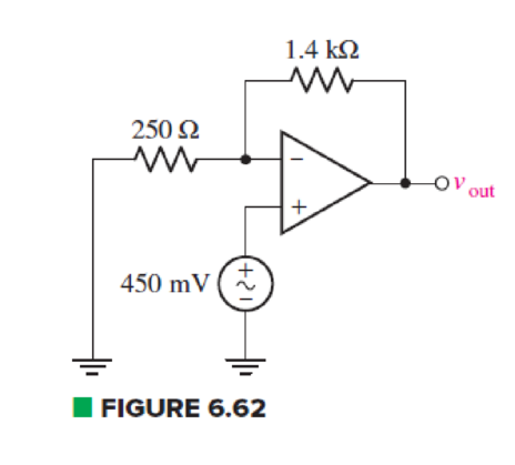
For the circuit of Fig. 6.62, calculate the differential input voltage and the input bias current if the op amp is a(n) (a) μA741; (b) LF411; (c) AD549K.
(a)
Find the differential input voltage and input bias current of op amp.
Answer to Problem 50E
The differential voltage
Explanation of Solution
Given Data:
Differential op amp is
Calculation:
The redrawn circuit of op amp is shown in Figure 1 as follows:
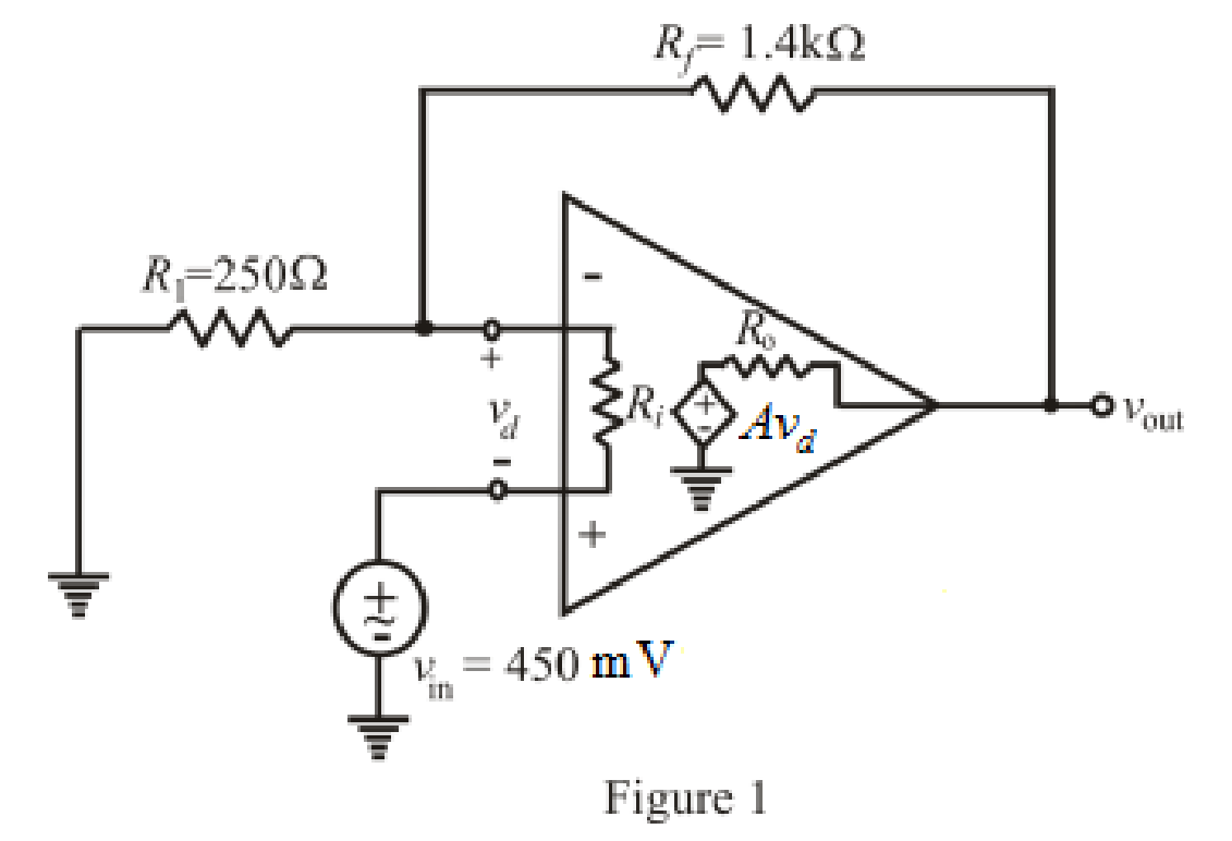
Refer to the redrawn Figure 1:
The expression for the nodal analysis at the nodal voltage
Here,
The expression for nodal analysis at nodal voltage
Here,
The expression for the bias input current of differential op amp is:
Here,
Simplify the equation (1) for
Refer to the TABLE 6.3 in the textbook.
Substitute
Rearrange for
Substitute
Substitute
Substitute
Rearrange for
Conclusion:
Thus, the differential voltage
(b)
Find the differential input voltage and input bias current of op amp.
Answer to Problem 50E
The differential voltage
Explanation of Solution
Given Data:
Differential op amp is
Calculation:
Refer to the TABLE 6.3 in the textbook.
Substitute
Rearrange for
Substitute
Substitute
Substitute
Rearrange for
Conclusion:
Thus, the differential voltage
(c)
Find the differential input voltage and input bias current of
Answer to Problem 50E
The differential voltage
Explanation of Solution
Given Data:
Differential op amp is
Calculation:
Refer to the TABLE 6.3 in the textbook.
Substitute
Rearrange for
Substitute
Substitute
Substitute
Rearrange for
Conclusion:
Thus, the differential voltage
Want to see more full solutions like this?
Chapter 6 Solutions
ENGINEERING CIRCUIT...(LL)>CUSTOM PKG.<
Additional Engineering Textbook Solutions
Starting Out with Java: From Control Structures through Objects (7th Edition) (What's New in Computer Science)
BASIC BIOMECHANICS
Database Concepts (8th Edition)
Electric Circuits. (11th Edition)
Concepts Of Programming Languages
Thermodynamics: An Engineering Approach


- PV Array Va DC/DC Converter Control Circuit ис V R Fig. 2. Principle of using DC/DC converter to implement electronic load [2] 4.5 1.5 -0.5 SEPIC Converters in SOM 0 0.2 0.4 0.6 0.8 Time SEPIC Converters in SOM M 0 0.2 0.4 0.6 0.8 Time Current I-V Curve (a) 8888888 P-V Curve 0 20 40 60 80 Voltage 0 20 40 60 Voltage 80 (b) Fig. 3. Experimental results of I-V and P-V curves [2]arrow_forwardR1 ww + R3 15+ www R2 R4 ww With the circuit diagram shown above and the values of the circuit elements listed below, find i1, 12, v1, and v2. Is = 10A, R1 = 7 ohms, R2 = 9 ohms, R3 = 7 ohms, R4 = 8 ohms (a) i1 = Number A (b) 12 = Number A (c) v1 = Number V (d) v2 = Number Varrow_forwardFind the equivalent resistance between terminals a and b in the circuit below where R₁ =6 N, R₂=12, R3=22, R4=22, and R5=150. 22 R2 R1 R5 oa R3 R4 ob Req= Number Ωarrow_forward
- A Thévenin equivalent can also be determined from measurements made at the pair of terminals of interest. Assume the following measurements were made at the terminals a,b in the figure below. When a 25 k2 resistor is connected to the terminals a,b, the voltage is measured and found to be 105 V. When a 2 k resistor is connected to the terminals a,b, the voltage is measured and found to be 13 V. Find the Thévenin equivalent of the network with respect to the terminals a,b. Linear resistive network with independent and dependent sources RTh = Number ΚΩ VTh= Number V a barrow_forwardI need help with this problem and an explanation of the solution for the image described below. (Introduction to Signals and Systems)arrow_forwardI need help with this problem and an explanation of the solution for the image described below. (Introduction to Signals and Systems)arrow_forward
- I need help with this problem and an explanation of the solution for the image described below. (Introduction to Signals and Systems)arrow_forwardI need help with this problem and an explanation of the solution for the image described below. (Introduction to Signals and Systems)arrow_forwardGiven 2 AWG, Aluminum, TW, 86 F, 2 Conductors, find Ampacityarrow_forward
 Introductory Circuit Analysis (13th Edition)Electrical EngineeringISBN:9780133923605Author:Robert L. BoylestadPublisher:PEARSON
 Delmar's Standard Textbook Of ElectricityElectrical EngineeringISBN:9781337900348Author:Stephen L. HermanPublisher:Cengage Learning
 Programmable Logic ControllersElectrical EngineeringISBN:9780073373843Author:Frank D. PetruzellaPublisher:McGraw-Hill Education
 Fundamentals of Electric CircuitsElectrical EngineeringISBN:9780078028229Author:Charles K Alexander, Matthew SadikuPublisher:McGraw-Hill Education
 Electric Circuits. (11th Edition)Electrical EngineeringISBN:9780134746968Author:James W. Nilsson, Susan RiedelPublisher:PEARSON
 Engineering ElectromagneticsElectrical EngineeringISBN:9780078028151Author:Hayt, William H. (william Hart), Jr, BUCK, John A.Publisher:Mcgraw-hill Education,