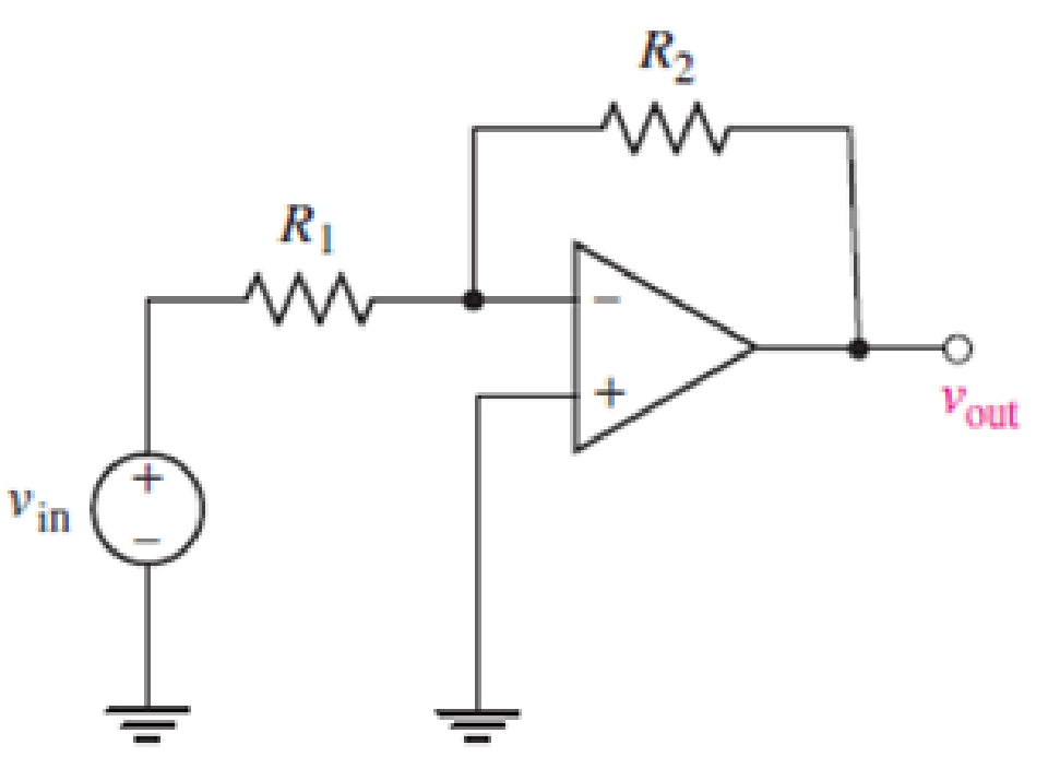
For the op amp circuit shown in Fig. 6.39, calculate vout if (a) R1 = R2 = 100 Ω, and vin = 5 V; (b) R2 = 200R1 and vin = 1 V; (c) R1 = 4.7 kΩ, R2 = 47 kΩ, and vin = 20 sin 5t V.

FIGURE 6.39
(a)
Find the value of
Answer to Problem 1E
The value of
Explanation of Solution
Formula used:
Refer to the FIGURE 6.39 in the Textbook.
The expression for the relation of
Here,
Calculation:
Refer to the FIGURE 6.39 in the Textbook.
Substitute
Conclusion:
Thus, the value of
(b)
Find the value of
Answer to Problem 1E
The value of
Explanation of Solution
Calculation:
Refer to the FIGURE 6.39 in the Textbook.
Substitute
Conclusion:
Thus, the value of
(c)
Find the value of
Answer to Problem 1E
The value of
Explanation of Solution
Calculation:
Refer to the FIGURE 6.39 in the TEXTBOOK.
Substitute
Conclusion:
Thus, the value of
Want to see more full solutions like this?
Chapter 6 Solutions
ENGINEERING CIRCUIT...(LL)>CUSTOM PKG.<
- I need a drawing on how to connect the function generator, oscilliscope, and both multimeters. It is hard for me to follow text instructions. The function generator has a postive,common and negative. The oscilliscope has chanell A and B, both channels have a postive and a negative. I know you can provide text instruction but a little sketch would be very helpful thank you.arrow_forwardDon't use ai to answer I will report you answerarrow_forwardQ1/ A three phase, 500 kVA, 6600 V, 50 Hz, 6 pole, star connected synchronous motor has synchronous impedance of J 70 ohm per phase at its normal rating, the motor is excited to give unity power factor at the input terminals. Find a) The rated current and power factor. b) The emf behind the synchronous impedance. c) The developed torque. d) The pull out torque. e) The increase in excitation which will just permit an increase of 30% of rated torque before pulling out of synchronism. (45 M.)arrow_forward
- can you fin Vds and Vgs of all transistors and specify te operating region off all transistors and prove it. 58V 5.8 V 1.8V M2 0.9V 22222 と A 4852 m 3 01 A Voy = 0.2 V V4)=0.SV λ=0.1 V-1arrow_forwardNeed a aolarrow_forward2 Find Inverse Fourier transform of F(jw) = 2w -16+w2, and plot the f(t).arrow_forward
 Introductory Circuit Analysis (13th Edition)Electrical EngineeringISBN:9780133923605Author:Robert L. BoylestadPublisher:PEARSON
 Delmar's Standard Textbook Of ElectricityElectrical EngineeringISBN:9781337900348Author:Stephen L. HermanPublisher:Cengage Learning
 Programmable Logic ControllersElectrical EngineeringISBN:9780073373843Author:Frank D. PetruzellaPublisher:McGraw-Hill Education
 Fundamentals of Electric CircuitsElectrical EngineeringISBN:9780078028229Author:Charles K Alexander, Matthew SadikuPublisher:McGraw-Hill Education
 Electric Circuits. (11th Edition)Electrical EngineeringISBN:9780134746968Author:James W. Nilsson, Susan RiedelPublisher:PEARSON
 Engineering ElectromagneticsElectrical EngineeringISBN:9780078028151Author:Hayt, William H. (william Hart), Jr, BUCK, John A.Publisher:Mcgraw-hill Education,


