
Videos
Obtain an expression for vout as labeled in the circuit of Fig. 6.50 if v1 equals (a) 0 V; (b) 1 V; (c) −5 V; (d) 2 sin 100t V.
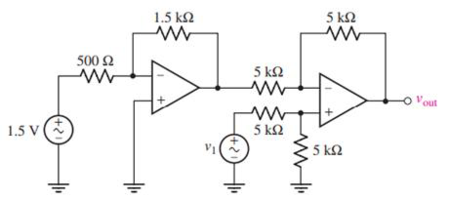
FIGURE 6.50
(a)
Find the output voltage
Answer to Problem 23E
The output voltage
Explanation of Solution
Given data:
The input voltage
Calculation:
The redrawn circuit is shown in Figure 1 as follows.
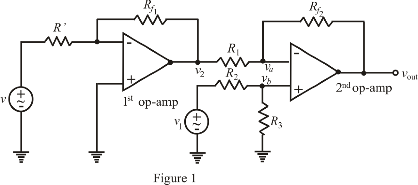
Refer to the Figure 1.
The expression of output voltage for 1st inverting op amp is,
Here,
The expression by the nodal analysis at node
Here,
The expression by the nodal analysis at node
Here,
The expression for the virtual ground concept is as follows,
Refer to the redrawn Figure 1.
Simplify equation (2) as follows.
Rearrange equation (3) for
Substitute
Rearrange for
Substitute for
Substitute
Conclusion:
Thus, the output voltage
(b)
Find the output voltage
Answer to Problem 23E
The output voltage
Explanation of Solution
Given data:
Value of input voltage
Calculation:
Refer to the redrawn Figure 1.
Substitute
Solve for
Conclusion:
Thus, the output voltage
(c)
Find the output voltage
Answer to Problem 23E
The output voltage
Explanation of Solution
Given data:
Value of input voltage
Calculation:
Refer to the redrawn Figure 1.
Substitute
Solve for
Conclusion:
Thus, the output voltage
(d)
Find the output voltage
Answer to Problem 23E
The output voltage
Explanation of Solution
Given data:
Value of input voltage
Calculation:
Refer to the redrawn Figure 1.
Substitute
Solve for
Conclusion:
Thus, the output voltage
Want to see more full solutions like this?
Chapter 6 Solutions
ENGINEERING CIRCUIT...(LL)>CUSTOM PKG.<


- Solve on paper not using chatgptarrow_forwardAssume that a building manager instructed you to install a water heater. The specs on the water heater nameplate reveals the following 240V, 2PH, 60HZ, 5.7KW. The manager insisted for the installation to be done with 10 AWG copper THWN-2 conductor, the length of run is 1200 FT away from the service panel. Calculate the voltage after the installation.arrow_forwardPlease confirm that my solution is correct, especially the block diagram. Please DRAW (not type) what the block diagram would look like if it's incorrect. thank youarrow_forward
- use this code on the bottom to answer the question in the photo clc; clearvars; % Read the file [y, Fs] = audioread('106miles.wav'); N = length(y); Nfft = 2^nextpow2(N); dt = 1/Fs; t = (0:dt:(N-1)*dt)'; % Ensure t is a column vector y = y - mean(y); % Remove DC component (if not already zero-mean) % Carrier signal (25 kHz) fc = 25000; % Carrier frequency in Hz carrier = cos(2 * pi * fc * t); % DSB-SC Modulation modulated_signal = y .* carrier; % Plot Time Domain Signal figure; subplot(2,1,1); plot(t, y); title('Original Signal (Time Domain)'); xlabel('Time (s)'); ylabel('Amplitude'); subplot(2,1,2); plot(t, modulated_signal); title('DSB-SC Modulated Signal (Time Domain)'); xlabel('Time (s)'); ylabel('Amplitude'); % Frequency Domain (FFT) Y = fft(y, Nfft) / Nfft; Modulated_Y = fft(modulated_signal, Nfft) / Nfft; f = Fs * (0:(Nfft/2)) / Nfft; % Frequency vector % Plot Frequency Domain Signal figure; subplot(2,1,1); plot(f, abs(Y(1:Nfft/2+1))); title('Original Signal…arrow_forward5-9 A 230 V shunt motor has a nominal arma- ture current of 60 A. If the armature resist- ance is 0.152, calculate the following: a. The counter-emf [V] b. The power supplied to the armature [W] c. The mechanical power developed by the motor, [kW] and [hp] 5-10 a. In Problem 5-9 calculate the initial start- ing current if the motor is directly con- nected across the 230 V line. b. Calculate the value of the starting resistor needed to limit the initial current to 115 A.arrow_forwardhow to solve this?arrow_forward
 Introductory Circuit Analysis (13th Edition)Electrical EngineeringISBN:9780133923605Author:Robert L. BoylestadPublisher:PEARSON
 Delmar's Standard Textbook Of ElectricityElectrical EngineeringISBN:9781337900348Author:Stephen L. HermanPublisher:Cengage Learning
 Programmable Logic ControllersElectrical EngineeringISBN:9780073373843Author:Frank D. PetruzellaPublisher:McGraw-Hill Education
 Fundamentals of Electric CircuitsElectrical EngineeringISBN:9780078028229Author:Charles K Alexander, Matthew SadikuPublisher:McGraw-Hill Education
 Electric Circuits. (11th Edition)Electrical EngineeringISBN:9780134746968Author:James W. Nilsson, Susan RiedelPublisher:PEARSON
 Engineering ElectromagneticsElectrical EngineeringISBN:9780078028151Author:Hayt, William H. (william Hart), Jr, BUCK, John A.Publisher:Mcgraw-hill Education,