
Videos
(a)
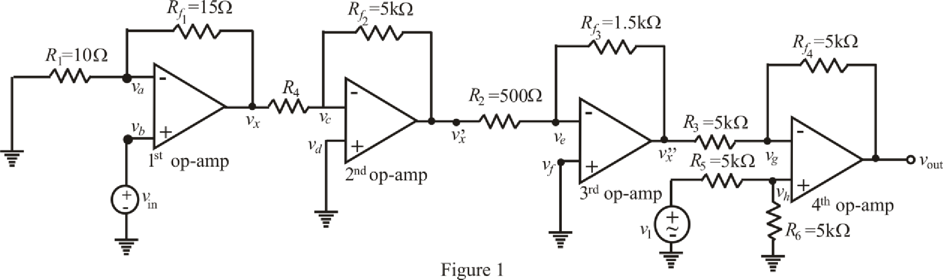
Find the output voltage of the circuit.
(a)
Answer to Problem 24E
The output voltage of combined circuit is
Explanation of Solution
Given data:
Combine the two circuits by eliminating the
Connect the output of circuit shown in FIGURE 6.49 to left-hand terminal of
Value of resistance
Value of input voltage of 1st op amp
Value of input voltage of 4th op amp
Calculation:
The redrawn circuit from given data is shown in Figure 1 as follows.
The expression for nodal analysis at node voltage
Here,
The expression for the virtual ground concept across 1st op amp is as follows.
Substitute
Rearrange for
Rearrange for
Substitute
Substitute
The expression for the nodal analysis at node voltage
Here,
The expression for the virtual ground concept across 2nd op amp is as follows,
Substitute
Rearrange for
Substitute
The expression for the nodal analysis at node voltage
Here,
The expression for the virtual ground concept across 3rd op amp is as follows.
Substitute
Rearrange for
Substitute
The expression for the nodal analysis at node voltage
Here,
The expression for the nodal analysis at node voltage
Here,
The expression for the virtual ground concept across 3rd op amp is as follows,
Simplify equation (14) for
Rearrange for
Substitute
Rearrange for
Rearrange for
Substitute
Solve for
Conclusion:
Thus, the output voltage of combined circuit is
(b)
Find the output voltage of the circuit.
(b)
Answer to Problem 24E
The output voltage of combined circuit is
Explanation of Solution
Given Data:
Value of resistance
Value of input voltage of 1st op amp
Value of input voltage of 4th op amp
Calculation:
Refer to the Figure 1,
Substitute
Substitute
Substitute
Substitute
Solve for
Conclusion:
Thus, the output voltage of combined circuit is
(c)
Find the output voltage of the circuit.
(c)
Answer to Problem 24E
The output voltage of combined circuit is
Explanation of Solution
Given Data:
Value of resistance
Value of input voltage of 1st op amp
Value of input voltage of 4th op amp
Calculation:
Refer to the Figure 1,
Substitute
Substitute
Substitute
Substitute
Solve for
Conclusion:
Thus, the output voltage of combined circuit is
Want to see more full solutions like this?
Chapter 6 Solutions
ENGINEERING CIRCUIT...(LL)>CUSTOM PKG.<


- Implement the ladder logic program needed to satisfy each of the following (assume inputs A, B and C are all normally open toggle switches). (a) When input A is closed, turn on output X, but hold on output Y until A opens. (b) When input A is closed and either input B or C is open, turn on output Y, otherwise it should be off. (c) When input A is closed or open, turn on output Y and turn off output X. (d) When input A is closed, turn on output X and turn off output Y.arrow_forward2. Find the inverse Laplace transform of the following s -domain signals. 1 a) Y(s) = (s+4)²(s+3) S+7 b) Y(s) = (s²+6s+13) s²+2s+2 c) Y(s) = (s+2)2-32 d) Y(s) = (1-es - e-3s) $2arrow_forward4. Answer the following questions. Take help from ChatGPT to answer these questions (if you need). But write the answers briefly using your own words with no more than two sentences and make sure you check whether ChatGPT is giving you the appropriate answers in our context. A) What is the zero-input response? B) What is the zero-state response? C) What are pole, zero, and residue in the context of our class? D) What are the different methods for finding the inverse Laplace transform? Which one we used in this class?arrow_forward
- 3. You have come to encounter an LTI system. You have no idea how the system behaves. So, you decide to drive the system with a particular input and measure the output. When you put the input u(t) = et 1(t), you find that the output y(t) = (1-e) 1(t). You can assume zero initial conditions. Now, find the transfer function of the system.arrow_forward1. Consider the following LTI system. d²y dy du +7 +6y= -- +2u, t≥0 dt² dt dt a) What is the impulse response of the system? Recall, h(t) = L-¹(H(s)). b) What are poles and zeros of the system? c) Suppose the initial condition of the system is y(0) = 1 and y'(0) = 4. What is the zero-input response of the system? d) Consider an input u(t) = (1 + et) 1(t) to the system. What is the zero-state response of the system for this input? e) Suppose, the initial condition was y(0) = -2 and y'(0) = -8 and the input is u(t)=(1+e) 1(t). What will be the total response of the system? You should be able to answer this using the linearity property of the system and your answers in part b and part c without taking any inverse Laplace transform.arrow_forwardGiven a normally distributed variable X with mean 4 and standard deviation 2, fi (a) P(X5). (d) P(1.8arrow_forwardTask 2 (2 credits) Consider the circuit in the figure below. The Zener diode has a Zener voltage of 15 V. What is the voltage Vout? 22 V 4.0 ΚΩ Vout 3.0 ΚΩarrow_forwardGiven a normally distributed variable X with mean 4 and standard deviation 2, fi (a) P(X5). (d) P(1.8arrow_forwardGiven a normally distributed variable X with mean 4 and standard deviation 2, fi (a) P(X5). (d) P(1.8arrow_forwardQ1. The three-phase full-wave converter in Figure shown is operated from a three phase Y-connected supply. Sketch the output voltages appeared at the load for firing angle 15°. I need Sketch an Ven จ T1 Q Yi₁ = I₂ a ia = is T₁ T3 T₂ Vbn b ib Load Highly inductive load ▲ T6 T₂ iT4 On T5, T6 T6, T₁ T2, T3 T3, T4 T4, T5 T5, T6 ཅ 0 T₁ الاسم T₁ Is wtarrow_forwardQ4. For the control system is shown in Figure 2, by using second method of Ziegler- Nichols, calculate the PID, PI-D and I-PD parameters and make tuning for this parameters to get accepting response for the هندسة الكم following system, then compare your results for all types controllers? R(S) K C(s) S3+4S² +11S Figure (2)arrow_forwardQ1. Consider the unity feedback control system whose open-loop transfer function is: G(s): = 40(S+2) s(s+3)(s+1)(s + 10) ELECTRIC Ziegler-Nichols, By using second method of Ziegler- Nichols, calculate the PID, PI-D and I-PD parameters and make tuning for this parameters to get accepting response for the following system, then comp controllers? PARTME then compare your results for all types GINEARIarrow_forwardarrow_back_iosSEE MORE QUESTIONSarrow_forward_iosRecommended textbooks for you
 Introductory Circuit Analysis (13th Edition)Electrical EngineeringISBN:9780133923605Author:Robert L. BoylestadPublisher:PEARSON
 Delmar's Standard Textbook Of ElectricityElectrical EngineeringISBN:9781337900348Author:Stephen L. HermanPublisher:Cengage Learning
 Programmable Logic ControllersElectrical EngineeringISBN:9780073373843Author:Frank D. PetruzellaPublisher:McGraw-Hill Education
 Fundamentals of Electric CircuitsElectrical EngineeringISBN:9780078028229Author:Charles K Alexander, Matthew SadikuPublisher:McGraw-Hill Education
 Electric Circuits. (11th Edition)Electrical EngineeringISBN:9780134746968Author:James W. Nilsson, Susan RiedelPublisher:PEARSON
 Engineering ElectromagneticsElectrical EngineeringISBN:9780078028151Author:Hayt, William H. (william Hart), Jr, BUCK, John A.Publisher:Mcgraw-hill Education,
Introductory Circuit Analysis (13th Edition)Electrical EngineeringISBN:9780133923605Author:Robert L. BoylestadPublisher:PEARSONDelmar's Standard Textbook Of ElectricityElectrical EngineeringISBN:9781337900348Author:Stephen L. HermanPublisher:Cengage LearningProgrammable Logic ControllersElectrical EngineeringISBN:9780073373843Author:Frank D. PetruzellaPublisher:McGraw-Hill EducationFundamentals of Electric CircuitsElectrical EngineeringISBN:9780078028229Author:Charles K Alexander, Matthew SadikuPublisher:McGraw-Hill EducationElectric Circuits. (11th Edition)Electrical EngineeringISBN:9780134746968Author:James W. Nilsson, Susan RiedelPublisher:PEARSONEngineering ElectromagneticsElectrical EngineeringISBN:9780078028151Author:Hayt, William H. (william Hart), Jr, BUCK, John A.Publisher:Mcgraw-hill Education,Inductors Explained - The basics how inductors work working principle; Author: The Engineering Mindset;https://www.youtube.com/watch?v=KSylo01n5FY;License: Standard Youtube License