
VECTOR MECH....F/ENGNRS-STATICS -CONNECT
12th Edition
ISBN: 9781260689495
Author: BEER
Publisher: MCG CUSTOM
expand_more
expand_more
format_list_bulleted
Concept explainers
Videos
Textbook Question
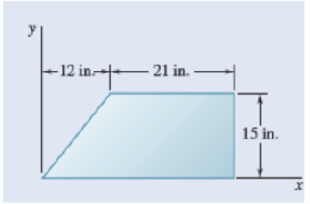
Chapter 5.1, Problem 5.2P
Locate the centroid of the plane area shown.
Expert Solution & Answer
Want to see the full answer?
Check out a sample textbook solution
Students have asked these similar questions
The tension in the belt is 46 lb. Determine the moment of the force F1 about the pin at A. Determine the moment of the force F2 about the pin at A.
1. Describe each of the tolerances in the following drawing:
0.01 A
09±0.025
.10±0.01
0.015 AB
6.76
08.51
03±0.05
0.015 MAB
14±0.03
60
14±0.02
12±0.08
0.01 A B
what is the intake flow in cfm of a 5.3 liter engine running at 6200 RPM with a volumetric efficiency of 86%. If we supercharge it to flow 610 CFM what is the volumetric efficiency?
Chapter 5 Solutions
VECTOR MECH....F/ENGNRS-STATICS -CONNECT
Ch. 5.1 - 5.1 through 5.9 Locate the centroid of the plane...Ch. 5.1 - Locate the centroid of the plane area shown.Ch. 5.1 - Locate the centroid of the plane area shown.Ch. 5.1 - Locate the centroid of the plane area shown.Ch. 5.1 - Locate the centroid of the plane area shown.Ch. 5.1 - Locate the centroid of the plane area shown.Ch. 5.1 - Locate the centroid of the plane area shown.Ch. 5.1 - Locate the centroid of the plane area shown.Ch. 5.1 - Locate the centroid of the plane area shown.Ch. 5.1 - Locate the centroid of the plane area shown.
Ch. 5.1 - Locate the centroid of the plane area shown.Ch. 5.1 - Locate the centroid of the plane area shown.Ch. 5.1 - Locate the centroid of the plane area shown.Ch. 5.1 - Locate the centroid of the plane area shown.Ch. 5.1 - Locate the centroid of the plane area shown.Ch. 5.1 - PROBLEM 5.16 Determine the y coordinate of the...Ch. 5.1 - Show that as r1 approaches r2, the location of the...Ch. 5.1 - For the area shown, determine the ratio a/b for...Ch. 5.1 - For the semiannular area of Prob. 5.12, determine...Ch. 5.1 - A built-up beam is constructed by nailing seven...Ch. 5.1 - The horizontal x axis is drawn through the...Ch. 5.1 - The horizontal x-axis is drawn through the...Ch. 5.1 - PROBLEM 5.23 The first moment of the shaded area...Ch. 5.1 - A thin, homogeneous wire is bent to form the...Ch. 5.1 - A thin, homogeneous wire is bent to form the...Ch. 5.1 - A thin, homogeneous wire is bent to form the...Ch. 5.1 - A thin, homogeneous wire is bent to form the...Ch. 5.1 - The homogeneous wire ABC is bent into a...Ch. 5.1 - The frame for a sign is fabricated from thin, flat...Ch. 5.1 - The homogeneous wire ABCD is bent as shown and is...Ch. 5.1 - The homogeneous wire ABCD is bent as shown and is...Ch. 5.1 - Determine the distance h for which the centroid of...Ch. 5.1 - Knowing that the distance h has been selected to...Ch. 5.2 - Determine by direct integration the centroid of...Ch. 5.2 - 5.34 through 5.36 Determine by direct integration...Ch. 5.2 - 5.34 through 5.36 Determine by direct integration...Ch. 5.2 - 5.37 through 5.39 Determine by direct integration...Ch. 5.2 - 5.37 through 5.39 Determine by direct integration...Ch. 5.2 - 5.37 through 5.39 Determine by direct integration...Ch. 5.2 - 5.40 and 5.41 Determine by direct integration the...Ch. 5.2 - 5.40 and 5.41 Determine by direct integration the...Ch. 5.2 - Determine by direct integration the centroid of...Ch. 5.2 - 5.43 and 5.44 Determine by direct integration the...Ch. 5.2 - 5.43 and 5.44 Determine by direct integration the...Ch. 5.2 - 5.45 and 5.46 A homogeneous wire is bent into the...Ch. 5.2 - 5.45 and 5.46 A homogeneous wire is bent into the...Ch. 5.2 - A homogeneous wire is bent into the shape shown....Ch. 5.2 - 5.48 and 5.49 Determine by direct integration the...Ch. 5.2 - 5.48 and 5.49 Determine by direct integration the...Ch. 5.2 - Determine the centroid of the area shown in terms...Ch. 5.2 - Determine the centroid of the area shown when a =...Ch. 5.2 - Determine the volume and the surface area of the...Ch. 5.2 - Determine the volume and the surface area of the...Ch. 5.2 - Determine the volume and the surface area of the...Ch. 5.2 - Determine the volume and the surface area of the...Ch. 5.2 - Determine the volume of the solid generated by...Ch. 5.2 - Verify that the expressions for the volumes of the...Ch. 5.2 - Knowing that two equal caps have been removed from...Ch. 5.2 - Three different drive belt profiles are to be...Ch. 5.2 - Determine the capacity, in liters, of the punch...Ch. 5.2 - Determine the volume and total surface area of the...Ch. 5.2 - Determine the volume and weight of the solid brass...Ch. 5.2 - Determine the total surface area of the solid...Ch. 5.2 - Determine the volume of the brass collar obtained...Ch. 5.2 - The shade for a wall-mounted light is formed from...Ch. 5.3 - 5.66 and 5.67 For the beam and loading shown,...Ch. 5.3 - 5.66 and 5.67 For the beam and loading shown,...Ch. 5.3 - 5.68 through 5.73 Determine the reactions at the...Ch. 5.3 - 5.68 through Determine the reactions at the beam...Ch. 5.3 - 5.68 through 5.73 Determine the reactions at the...Ch. 5.3 - 5.68 through Determine the reactions at the beam...Ch. 5.3 - 5.68 through 5.73 Determine the reactions at the...Ch. 5.3 - 5.68 through 5.73 Determine the reactions at the...Ch. 5.3 - Determine (a) the distance a so that the vertical...Ch. 5.3 - Determine (a) the distance a so that the reaction...Ch. 5.3 - Determine the reactions at the beam supports for...Ch. 5.3 - Determine (a) the distributed load w0 at the end D...Ch. 5.3 - The beam AB supports two concentrated loads and...Ch. 5.3 - For the beam and loading of Prob. 5.78, determine...Ch. 5.3 - The cross section of a concrete dam is as shown....Ch. 5.3 - The cross section of a concrete dam is as shown....Ch. 5.3 - The dam for a lake is designed to withstand the...Ch. 5.3 - The base of a dam for a lake is designed to resist...Ch. 5.3 - Prob. 5.84PCh. 5.3 - Prob. 5.85PCh. 5.3 - The 3 4-m side AB of a tank is hinged at its...Ch. 5.3 - The 3 4-m side of an open tank is hinged at its...Ch. 5.3 - A 0.5 0.8-m gate AB is located at the bottom of a...Ch. 5.3 - A 0.5 0.8-m gate AB is located at the bottom of a...Ch. 5.3 - A 4 2-ft gate is hinged at A and is held in...Ch. 5.3 - Fig. P5.90 5.91 Solve Prob. 5.90 if the gate...Ch. 5.3 - A prismatically shaped gate placed at the end of a...Ch. 5.3 - A prismatically shaped gate placed at the end of a...Ch. 5.3 - A long trough is supported by a continuous hinge...Ch. 5.3 - The square gate AB is held in the position shown...Ch. 5.4 - Consider the composite body shown. Determine (a)...Ch. 5.4 - A cone and a cylinder of the same radius a and...Ch. 5.4 - Determine the location of the center of gravity of...Ch. 5.4 - Prob. 5.99PCh. 5.4 - For the stop bracket shown, locate the x...Ch. 5.4 - Fig. P5.100 and P5.101 5.101 For the stop bracket...Ch. 5.4 - Prob. 5.102PCh. 5.4 - Prob. 5.103PCh. 5.4 - For the machine element shown, locate the y...Ch. 5.4 - For the machine element shown, locate the x...Ch. 5.4 - 5.106 and 5.107 Locate the center of gravity of...Ch. 5.4 - 5.106 and 5.107 Locate the center of gravity of...Ch. 5.4 - A corner reflector for tracking by radar has two...Ch. 5.4 - A wastebasket, designed to fit in the corner of a...Ch. 5.4 - An elbow for the duct of a ventilating system is...Ch. 5.4 - A window awning is fabricated from sheet metal...Ch. 5.4 - Locate the center of gravity of the sheet-metal...Ch. 5.4 - Locate the center of gravity of the sheet-metal...Ch. 5.4 - A thin steel wire with a uniform cross section is...Ch. 5.4 - The frame of a greenhouse is constructed from...Ch. 5.4 - Locate the center of gravity of the figure shown,...Ch. 5.4 - Prob. 5.117PCh. 5.4 - A scratch awl has a plastic handle and a steel...Ch. 5.4 - PROBLEM 5.117 A bronze bushing is mounted inside a...Ch. 5.4 - PROBLEM 5.120 A brass collar, of length 2.5 in.,...Ch. 5.4 - PROBLEM 5.121 The three legs of a small...Ch. 5.4 - Prob. 5.122PCh. 5.4 - Determine by direct integration the values of x...Ch. 5.4 - Prob. 5.124PCh. 5.4 - PROBLEM 5.125 Locate the centroid of the volume...Ch. 5.4 - Prob. 5.126PCh. 5.4 - Prob. 5.127PCh. 5.4 - PROBLEM 5.128 Locate the centroid of the volume...Ch. 5.4 - PROBLEM 5.129 Locate the centroid of the volume...Ch. 5.4 - Show that for a regular pyramid of height h and n...Ch. 5.4 - PROBLEM 5.131 Determine by direct integration the...Ch. 5.4 - PROBLEM 5.132 The sides and the base of a punch...Ch. 5.4 - Locate the centroid of the section shown, which...Ch. 5.4 - Locate the centroid of the section shown, which...Ch. 5.4 - Determine by direct integration the location of...Ch. 5.4 - Alter grading a lot, a builder places four stakes...Ch. 5 - 5.137 and 5.138 Locate the centroid of the plane...Ch. 5 - 5.137 and 5.138 Locate the centroid of the plane...Ch. 5 - Prob. 5.139RPCh. 5 - Determine by direct integration the centroid of...Ch. 5 - Determine by direct integration the centroid of...Ch. 5 - The escutcheon (a decorative plate placed on a...Ch. 5 - Determine the reactions at the supports for the...Ch. 5 - A beam is subjected to a linearly distributed...Ch. 5 - A tank is divided into two sections by a 1 1-m...Ch. 5 - Determine the y coordinate of the centroid of the...Ch. 5 - An 8-in.-diameter cylindrical duct and a 4 8-in....Ch. 5 - Three brass plates are brazed to a steel pipe to...
Knowledge Booster


Learn more about
Need a deep-dive on the concept behind this application? Look no further. Learn more about this topic, mechanical-engineering and related others by exploring similar questions and additional content below.Similar questions
- Quiz/An eccentrically loaded bracket is welded to the support as shown in Figure below. The load is static. The weld size for weld w1 is h1=6mm, for w2 h2 5mm, and for w3 is h3 -5.5 mm. Determine the safety factor (S.f) for the welds. F=22 kN. Use an AWS Electrode type (E90xx). 140 101.15 REDMI NOTE 8 PRO AI QUAD CAMERA Farrow_forwardQuiz/An eccentrically loaded bracket is welded to the support as shown in Figure below. The load is static. The weld size for weld w1 is h1 = 4mm, for w2 h2 = 6mm, and for w3 is h3 -6.5 mm. Determine the safety factor (S.f) for the welds. F=29 kN. Use an AWS Electrode type (E100xx). BES FOR P 163 mm 133 mm 140 mmarrow_forwardExample -4s F(s) = = (s²+4)² As + B Cs+D + (s²+4) (s²+4)² (s²+4) (H.W)arrow_forward
- Q1/ Find L[t et sin t] Q2/ Find The Laplace Transform f(t) = [sint [sint 0arrow_forwardb) The 50 mm diameter rod is placed in a hole, lubricated walls. There is no clearance between the rod and the sides of the hole. Determine the change in length of the rod if an 8 kN load is applied. Take E(brass) = 80 GPa; v = 0.55 [10] 50 mmm 300 rat 3arrow_forwardThe Mach number NM for flow of a perfect gas in a pipe depends upon the specific-heat ratio k (dimensionless), the pressure p, the density ρ, and the velocity V. Obtain by dimensional reasoning the form of the Mach number expression. (Buckingham pi)Answer: NM = f(V/sqrt(p/ρ), k)arrow_forwardoyfr 3. The figure shows a frame under the influence of an external loading made up of five forces and two moments. Use the scalar method to calculate moments. a. Write the resultant force of the external loading in Cartesian vector form. b. Determine the & direction of the resultant moment of the external loading about A. 15 cm 18 cm 2.2 N-m B 50 N 45° 10 cm 48 N.m 250 N 60 N 20 21 50 N 25 cm 100 N A 118, 27cm 5, 4:1arrow_forwardAssume the Link AO is the input and revolves 360°, determine a. the coordinates of limit positions of point B, b. the angles (AOC) corresponding to the limit positionsarrow_forwardoyfr 3. The figure shows a frame under the influence of an external loading made up of five forces and two moments. Use the scalar method to calculate moments. a. Write the resultant force of the external loading in Cartesian vector form. b. Determine the & direction of the resultant moment of the external loading about A. 15 cm 18 cm 2.2 N-m B 50 N 45° 10 cm 48 N.m 250 N 60 N 20 21 50 N 25 cm 100 N A 118, 27cm 5, 4:1arrow_forwardThe 2-mass system shown below depicts a disk which rotates about its center and has rotational moment of inertia Jo and radius r. The angular displacement of the disk is given by 0. The spring with constant k₂ is attached to the disk at a distance from the center. The mass m has linear displacement & and is subject to an external force u. When the system is at equilibrium, the spring forces due to k₁ and k₂ are zero. Neglect gravity and aerodynamic drag in this problem. You may assume the small angle approximation which implies (i) that the springs and dampers remain in their horizontal / vertical configurations and (ii) that the linear displacement d of a point on the edge of the disk can be approximated by d≈re. Ө K2 www m 4 Cz 777777 Jo Make the following assumptions when analyzing the forces and torques: тв 2 0>0, 0>0, x> > 0, >0 Derive the differential equations of motion for this dynamic system. Start by sketching LARGE and carefully drawn free-body-diagrams for the disk and the…arrow_forwardA linear system is one that satisfies the principle of superposition. In other words, if an input u₁ yields the output y₁, and an input u2 yields the output y2, the system is said to be linear if a com- bination of the inputs u = u₁ + u2 yield the sum of the outputs y = y1 + y2. Using this fact, determine the output y(t) of the following linear system: given the input: P(s) = = Y(s) U(s) = s+1 s+10 u(t) = e−2+ sin(t) =earrow_forwardThe manometer fluid in the figure given below is mercury where D = 3 in and h = 1 in. Estimate the volume flow in the tube (ft3/s) if the flowing fluid is gasoline at 20°C and 1 atm. The density of mercury and gasoline are 26.34 slug/ft3 and 1.32 slug/ft3 respectively. The gravitational force is 32.2 ft/s2.arrow_forwardarrow_back_iosSEE MORE QUESTIONSarrow_forward_ios
Recommended textbooks for you
 International Edition---engineering Mechanics: St...Mechanical EngineeringISBN:9781305501607Author:Andrew Pytel And Jaan KiusalaasPublisher:CENGAGE L
International Edition---engineering Mechanics: St...
Mechanical Engineering
ISBN:9781305501607
Author:Andrew Pytel And Jaan Kiusalaas
Publisher:CENGAGE L
Mechanical Engineering: Centroids & Center of Gravity (1 of 35) What is Center of Gravity?; Author: Michel van Biezen;https://www.youtube.com/watch?v=Tkyk-G1rDQg;License: Standard Youtube License