
International Edition---engineering Mechanics: Statics, 4th Edition
4th Edition
ISBN: 9781305501607
Author: Andrew Pytel And Jaan Kiusalaas
Publisher: CENGAGE L
expand_more
expand_more
format_list_bulleted
Concept explainers
Videos
Textbook Question
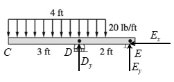
Chapter 4, Problem 4.11P
The figure is a model for member CDE of the frame described in Prob. 4.10. Draw the FBD of the member, neglecting its weight. Count the unknowns.
Expert Solution & Answer
Want to see the full answer?
Check out a sample textbook solution
Students have asked these similar questions
M16x2 grade 8.8 bolts No. 25 C1-
Q.2. The figure is a cross section of a grade 25 cast-iron pressure vessel. A
total of N, M16x2.0 grade 8.8 bolts are to be used to resist a separating
force of 160 kN. (a) Determine ks, km, and C. (b) Find the number of bolts
required for a load factor of 2 where the bolts may be reused when the joint 19 mm
is taken apart. (c) with the number of bolts obtained in (b), determine the
realized load factor for overload, the yielding factor of safety, and the
separation factor of safety.
19 mm
Problem4.
The thin uniform disk of mass m = 1-kg and radius R = 0.1m spins about the bent shaft OG with
the angular speed w2 = 20 rad/s. At the same time, the shaft rotates about the z-axis with the angular
speed 001 = 10 rad/s. The angle between the bent portion of the shaft and the z-axis is ẞ = 35°. The
mass of the shaft is negligible compared to the mass of the disk.
a. Find the angular momentum of the disk with respect to point G, based on the axis
orientation as shown. Include an MVD in your solution.
b. Find the angular momentum of the disk with respect to point O, based on the axis
orientation as shown. (Note: O is NOT the center of fixed-point rotation.)
c. Find the kinetic energy of the assembly.
z
R
R
002
2R
x
Answer: H = -0.046ĵ-0.040 kg-m²/sec
Ho=-0.146-0.015 kg-m²/sec
T 0.518 N-m
=
Problem 3.
The assembly shown consists of a solid sphere of mass m and the uniform slender rod of the same
mass, both of which are welded to the shaft. The assembly is rotating with angular velocity w at a
particular moment. Find the angular momentum with respect to point O, in terms of the axes
shown.
Answer: Ñ。 = ½mc²wcosßsinßĵ + (}{mr²w + 2mb²w + ½ mc²wcos²ß) k
3
m
r
b
2
C
لا
m
Chapter 4 Solutions
International Edition---engineering Mechanics: Statics, 4th Edition
Ch. 4 - Each of the bodies shown is homogeneous and has a...Ch. 4 - Each of the bodies shown is homogeneous and has a...Ch. 4 - Each of the bodies shown is homogeneous and has a...Ch. 4 - The homogeneous bar weighs 12 lb. It is resting on...Ch. 4 - The homogeneous beam AB weighs 400 lb. For each...Ch. 4 - The homogeneous triangular plate has a mass of 12...Ch. 4 - The bracket of negligible weight is supported by a...Ch. 4 - The figure models the handle of the water cock...Ch. 4 - The high-pressure water cock is rigidly attached...Ch. 4 - Draw the FBD of the entire frame, assuming that...
Ch. 4 - The figure is a model for member CDE of the frame...Ch. 4 - The homogeneous cylinder of weight Wrests in a...Ch. 4 - Calculate the force P that is required to hold the...Ch. 4 - The 60-lb homogeneous disk is suspended from a...Ch. 4 - The 180-kg uniform boom ABC, supported by a...Ch. 4 - The table lamp consists of two uniform arms, each...Ch. 4 - At what angle will the lamp in Prob. 4.16 be in...Ch. 4 - The bent beam ABC is supported by a pin at B and a...Ch. 4 - Compute all reactions at the base A of the traffic...Ch. 4 - The man is holding up the 35-kg ladder ABC by...Ch. 4 - The 1200-lb homogeneous block is placed on rollers...Ch. 4 - The uniform plank ABC weighs 400 N. It is...Ch. 4 - The center of gravity of the 850-N man is at G. If...Ch. 4 - The homogeneous 340-lb sign is suspended from...Ch. 4 - When the truck is empty, it weighs 6000 lb and its...Ch. 4 - The homogeneous bar AB weighs 25 lb. Determine the...Ch. 4 - Determine the smallest horizontal force P that...Ch. 4 - The homogeneous beam AB weighing 800 lb carries...Ch. 4 - The homogeneous 40-kg bar ABC is held in position...Ch. 4 - The horizontal force P is applied to the handle of...Ch. 4 - The homogeneous plate of weight W is suspended...Ch. 4 - Neglecting the mass of the beam, compute the...Ch. 4 - The 1200-kg car is being lowered slowly onto the...Ch. 4 - The crate weighing 400 lb is supported by three...Ch. 4 - Find the smallest value of P for which the crate...Ch. 4 - Determine the rope tension T for which the pulley...Ch. 4 - The 40-kg homogeneous disk is resting on an...Ch. 4 - The 40-kghomogeneous disk is placed on a...Ch. 4 - The mass of the uniform bar AB is 80 kg. Calculate...Ch. 4 - The mechanism shown is a modified Geneva drive-a...Ch. 4 - The center of gravity of the 3000-lb car is at G....Ch. 4 - The 30-lb block is held in place on the smooth...Ch. 4 - The vertical post is supported by two cables (the...Ch. 4 - The uniform ladder of weight W is raised slowly by...Ch. 4 - The uniform, 30-lb ladder is raised slowly by...Ch. 4 - The 90-kg man, whose center of gravity is at G, is...Ch. 4 - The bar ABC is constrained by the pin support A...Ch. 4 - The tensioning mechanism of a magnetic tape drive...Ch. 4 - The homogeneous 300-kg cylinder is pulled over the...Ch. 4 - Compute the magnitudes of the reactions at pin A...Ch. 4 - Each of the sandbags piled on the 380-lb uniform...Ch. 4 - The 18-ft pole is supported by a pin at A and a...Ch. 4 - The supporting structure of the billboard is...Ch. 4 - The self-regulating floodgate ABC, pinned at B, is...Ch. 4 - The cantilever beam is built into a wall at O....Ch. 4 - Determine the force F required to keep the 200-kg...Ch. 4 - The uniform rod AB of weight W is supported by the...Ch. 4 - A machine operator produces the tension Tin the...Ch. 4 - The dump truck consists of a chassis and a tray,...Ch. 4 - The centers of gravity of the 50-kg lift truck and...Ch. 4 - (a) draw the free-body diagrams for the entire...Ch. 4 - (a) draw the free-body diagrams for the entire...Ch. 4 - For Probs. 4.61–4.68, (a) draw the free-body...Ch. 4 - (a) draw the free-body diagrams for the entire...Ch. 4 - (a) draw the free-body diagrams for the entire...Ch. 4 - (a) draw the free-body diagrams for the entire...Ch. 4 - (a) draw the free-body diagrams for the entire...Ch. 4 - (a) draw the free-body diagrams for the entire...Ch. 4 - The two uniform cylinders, each of weight W, are...Ch. 4 - Draw the FBDs for the following: (a) bar ABC with...Ch. 4 - Draw the FBDs for the beam ABC and the segments AB...Ch. 4 - Draw the FBDs for the entire structure and the...Ch. 4 - The beam consists of the bars AB and BC connected...Ch. 4 - For the frame shown, determine the magnitude of...Ch. 4 - Determine the magnitudes of the pin reactions at A...Ch. 4 - The bars AB and AC are joined by a pin at A and a...Ch. 4 - Neglecting the weights of the members, determine...Ch. 4 - Calculate the magnitudes of the pin reactions at A...Ch. 4 - Determine the magnitude of the pin reaction at A...Ch. 4 - Neglecting friction and the weights of the...Ch. 4 - When activated by the force P, the gripper on a...Ch. 4 - Determine the axle loads (normal forces at A, B,...Ch. 4 - Determine the force P that would produce a tensile...Ch. 4 - The pulley-cable system supports the 150-lb...Ch. 4 - Determine the contact force between the smooth...Ch. 4 - Compute the tension in the cable and the contact...Ch. 4 - Determine the magnitude of the pin reaction at B....Ch. 4 - Determine the tension in the cable at B, given...Ch. 4 - Compute the magnitude of the pin reaction at B....Ch. 4 - Neglecting the weight of the frame, find the...Ch. 4 - Determine the clamping force at A due to the 15-lb...Ch. 4 - Compute the tension in the cable BD when the...Ch. 4 - Calculate the reactions at the built-in support at...Ch. 4 - Determine the magnitudes of the roller reactions...Ch. 4 - The linkage of the braking system consists of the...Ch. 4 - The window washers A and B support themselves and...Ch. 4 - The figure shows a wire cutter. Determine the...Ch. 4 - Find the tension T in the cable when the 180-N...Ch. 4 - The 400-kg drum is held by tongs of negligible...Ch. 4 - Compute the magnitudes of all forces acting on...Ch. 4 - Calculate all forces acting on member CDB.Ch. 4 - The automatic drilling robot must sustain a thrust...Ch. 4 - Determine the clamping (vertical) force applied by...Ch. 4 - Determine the axial force in member BC of the...Ch. 4 - Neglecting friction, determine the relationship...Ch. 4 - Find the magnitudes of the pin reactions at A and...Ch. 4 - The load in the bucket of a skid steer loader is...Ch. 4 - Determine the magnitude of the roller reaction at...Ch. 4 - The tool shown is used to crimp terminals onto...Ch. 4 - The 12-lb force is applied to the handle of the...Ch. 4 - The blade of the bulldozer is rigidly attached to...Ch. 4 - Find the magnitudes of the pin reactions at A, C,...Ch. 4 - The pins at the end of the retaining-ring spreader...Ch. 4 - Determine the magnitudes of the support reactions...Ch. 4 - Find the magnitude of the pin reaction at C....Ch. 4 - For the pliers shown, determine the relationship...Ch. 4 - The device shown is an overload prevention...Ch. 4 - The figure is a schematic of a wire cutter....Ch. 4 - The hinge shown is the type used on the doors of...Ch. 4 - Determine the force in the hydraulic cylinder EF...Ch. 4 - Determine the horizontal force P that would keep...Ch. 4 - Determine the magnitudes of the forces acting on...Ch. 4 - Determine the angle at which the bar AB is in...Ch. 4 - The automobile, with center of gravity at G, is...Ch. 4 - The figure shows a three-pin arch. Determine the...Ch. 4 - The center of gravity of the nonhomogeneous bar AB...Ch. 4 - When suspended from two cables, the rocket assumes...Ch. 4 - The pump oiler is operated by pressing on the...Ch. 4 - The uniform 240-lb bar AB is held in the position...Ch. 4 - Find the force P required to (a) push; and (b)...Ch. 4 - Using the method of joints, calculate the force in...Ch. 4 - Using the method of joints, calculate the force in...Ch. 4 - Using the method of joints, calculate the force in...Ch. 4 - Using the method of joints, calculate the force in...Ch. 4 - Using the method of joints, calculate the force in...Ch. 4 - Using the method of joints, calculate the force in...Ch. 4 - Using the method of joints, calculate the force in...Ch. 4 - Using the method of joints, calculate the force in...Ch. 4 - Using the method of joints, calculate the force in...Ch. 4 - Using the method of joints, calculate the force in...Ch. 4 - Identify all the zero-force members in the four...Ch. 4 - The walkway ABC of the footbridge is stiffened by...Ch. 4 - Find the force in member EF.Ch. 4 - Determine the forces in members AE, BE, and ED.Ch. 4 - Determine the reaction at E and the force in each...Ch. 4 - Determine the force in member AD of the truss.Ch. 4 - Determine the force in member BE of the truss.Ch. 4 - Show that all diagonal members of the truss carry...Ch. 4 - Determine the forces in members FG and AB in terms...Ch. 4 - Determine the forces in members BC, BG, and FG.Ch. 4 - Determine the forces in members EF, BF, and BC.Ch. 4 - Compute the forces in members EF, NE and NO.Ch. 4 - Repeat Prob. 4.152 assuming that the 400-kN force...Ch. 4 - Determine the forces in members BG, CI, and CD.Ch. 4 - Assuming that P=48000lb and that it may be applied...Ch. 4 - Calculate the forces in members BC, CF, and FG.Ch. 4 - Find the forces in members CD, DH, and HI.Ch. 4 - Determine the forces in members CD and DF.Ch. 4 - Compute the forces in members CD and JK, given...Ch. 4 - If PCD=6000lb and PGD=1000lb (both compression),...Ch. 4 - Determine the forces in members EF, BF, and BC.Ch. 4 - Determine the forces in members AC, AD, and DE.Ch. 4 - Determine the forces in members GI, PH, and GH....Ch. 4 - Determine the forces in members CD, IJ, and NJ of...Ch. 4 - Calculate the forces in members AB and DE.Ch. 4 - (a) Find the forces in members CE, CF, and DF. (b)...Ch. 4 - Determine the forces in members BC and BE and the...Ch. 4 - A couple acting on the winch at G slowly raises...Ch. 4 - The uniform, 20-kg bar is placed between two...Ch. 4 - The 320-lb homogeneous spool is placed on the...Ch. 4 - Determine the magnitude of the pin reaction at A,...Ch. 4 - Determine the couple C that will hold the bar AB...Ch. 4 - The 800-lb force is applied to the pin at E....Ch. 4 - The weight W=6kN hangs from the cable which passes...Ch. 4 - The 2000-lb and 6000-lb forces are applied to the...Ch. 4 - The two couples act at the midpoints of bars AB...Ch. 4 - Determine the forces in members AC and AD of the...Ch. 4 - Determine the angle for which the uniform bar of...Ch. 4 - Determine the magnitude of the force exerted by...Ch. 4 - Calculate the forces in members (a) DE; (b) BE;...Ch. 4 - Determine the ratio P/Q for which the parallel...Ch. 4 - The 30-lb block C rests on the uniform 14-lb bar...Ch. 4 - The 30-lb homogeneous bar AB supports the 60-lb...Ch. 4 - Determine the forces in members (a) EF; and (b)...Ch. 4 - Find the magnitude of the pin reaction at B caused...Ch. 4 - The breaking strength of the cable FG that...Ch. 4 - Determine the forces in members GH, BH, and BC of...Ch. 4 - The 80-N force is applied to the handle of the...Ch. 4 - The tongs shown are designed for lifting blocks of...
Knowledge Booster


Learn more about
Need a deep-dive on the concept behind this application? Look no further. Learn more about this topic, mechanical-engineering and related others by exploring similar questions and additional content below.Similar questions
- I have Euler parameters that describe the orientation of N relative to Q, e = -0.7071*n3, e4 = 0.7071. I have Euler parameters that describe the orientation of U relative to N, e = -1/sqrt(3)*n1, e4 = sqrt(2/3). After using euler parameter rule of successive rotations, I get euler parameters that describe the orientation of U relative to Q, e = -0.4082*n1 - 0.4082*n2 - 0.5774*n3. I need euler parameters that describe the orientation of U relative to Q in vector basis of q instead of n. How do I get that?arrow_forwardDescribe at least 4 processes in engineering where control charts are (or should be) appliedarrow_forwardDescribe at least two (2) processes where control charts are (or should be) applied.arrow_forward
- Problem 3: A cube-shaped spacecraft is in a circular Earth orbit. Let N (n,) be inertial and the spacecraft is denoted S (ŝ₁). The spacecraft is described such that ¯½º = J ŝ₁ŝ₁ + J ŝ₂§₂ + J §¸Ŝ3 Location of the spacecraft in the orbit is determined by the orbit-fixed unit vectors ê, that are oriented by the angle (Qt), where is a constant angular rate. 52 €3 3> 2t 55 Λ Из At the instant when Qt = 90°, the spacecraft S is oriented relative to the orbit such that 8₁ = 0° Space-three 1-2-3 angles 0₂ = 60° and ES = $₂ rad/s 0₁ = 135° (a) At this instant, determine the direction cosine matrix that describes the orientation of the spacecraft with respect to the inertial frame N.arrow_forwardThis problem illustrates that the factor of safety for a machine element depends on the particular point selected for analysis. Here you are to compute factors of safety, based upon the distortion-energy theory, for stress elements at A and B of the member shown in the figure. This bar is made of AISI 1006 cold-drawn steel and is loaded by the forces F = 1.100 kN, P = 8.00 kN, and T = 50.00 N-m. Given: Sy = 280 MPa. B -100 mm- 15-mm D. a) Determine the value of the axial stress at point B. b) Determine the value of the shear stress at point B. c) Determine the value of the Von Mises stress at point B. P Farrow_forwardA piston-cylinder device initially contains 0.08 m^3 of nitrogen gas at 130 kPa and 170°C. The nitrogen is expanded to a pressure of 80 kPa via isentropic expansion. Determine the final temperature and the boundary work done by the system during this process.arrow_forward
- A Carnot (ideal) heat pump is to be used to heat a house and maintain it at 22°C in winter. On a day when the average outdoor temperature remains at about 0°C, the house is estimated to lose heat at a rate of 65,000 kJ/h. If the heat pump consumes 6 kW of power while operating, determine: (a) how long the heat pump ran on that day (b) the total heating costs, assuming an average price of 11¢/kWh for electricity (c) the heating cost for the same day if an 85% efficient electric furnace is used instead of a heat pump.arrow_forwardFrom the information in the image, I needed to find the orientation of U relative to Q in vector basis q_hat. I transformed the euler angle/axis representation to euler parameters. Then I got its conjugate in order to get the euler parameter in N frame relative to Q. The problem gave the euler angle/axis representation in Q frame relative to N, so I needed to find the conjugate. Then I used the euler parameter rule of successive rotation to find the final euler parameters that describe the orientation of U relative to Q. However that orientation is in n_hat which is the intermediate frame. How do I get the final result in q_hat?arrow_forwardA proposed method of power generation involves collecting and storing solar energy in large artificial lakes a few meters deep, called solar ponds. Solar energy is absorbed by all parts of the pond, and the water temperature rises everywhere. The top part of the pond, however, loses much of the heat it absorbs to the atmosphere, and as a result, the cool surface water serves as insulation for the bottom part of the pond and helps trap the energy there. Usually, salt is planted at the bottom of the pond to prevent the rise of this hot water to the top. A heat engine that uses an organic fluid, such as alcohol, as the working fluid can be operated between the top and the bottom portions of the pond. If the water temperature is 27°C near the surface and 72°C near the bottom of the pond, determine the maximum thermal efficiency that this power plant can have. Treat the cycle as an ideal heat engine. Would a heat engine operating under these temperature conditions (27°C and 72°C) be…arrow_forward
arrow_back_ios
SEE MORE QUESTIONS
arrow_forward_ios
Recommended textbooks for you
 International Edition---engineering Mechanics: St...Mechanical EngineeringISBN:9781305501607Author:Andrew Pytel And Jaan KiusalaasPublisher:CENGAGE L
International Edition---engineering Mechanics: St...
Mechanical Engineering
ISBN:9781305501607
Author:Andrew Pytel And Jaan Kiusalaas
Publisher:CENGAGE L
Solids: Lesson 53 - Slope and Deflection of Beams Intro; Author: Jeff Hanson;https://www.youtube.com/watch?v=I7lTq68JRmY;License: Standard YouTube License, CC-BY