
Videos
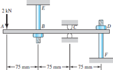
The steel beam ABCD shown is simply supported at C as shown and supported at B and D by shoulder steel bolts, each having a diameter of 8 mm. The lengths of BE and DF are 50 mm and 65 mm, respectively. The beam has a second area moment of 21(103) mm4. Prior to loading, the members are stress-free. A force of 2 kN is then applied at point A. Using procedure 2 of Sec. 4–10, determine the stresses in the bolts and the deflections of points A, B, and D.
Problem 4–102
The stresses in the bolts.
The deflection at point A.
The deflection at point B.
The deflection at point D.
Answer to Problem 102P
The stress in the bolt
The deflection at point A is
The deflection at point B is
The deflection at point D is
Explanation of Solution
The Figure (1) shows the free body diagram of the steel beam ABCD.
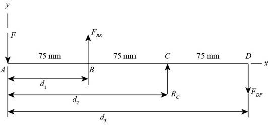
Figure (1)
Here, the applied load at point
Refer to procedure 2 from Sec. 4–10.
Write the expression for the net force in the beam
Write the expression for the net moment about point
Here, the length of the beam is
The Figure (2) shows the beam at section (1).
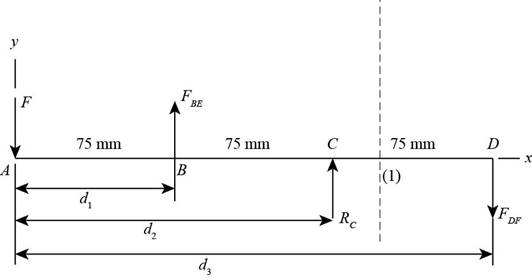
Figure (2)
Write the expression for the bending moment at section (1).
Here, the bending moment at section (1) is
Write the expression for the bending moment in terms of elastic equation.
Here, the modulus of elasticity is
Substitute
Integrate the above expression.
Further integrate the above expression.
Write the expression for the area of the bolt.
Here, the area of the bolt is
Write the expression for elongationin the steel boltat point B.
Here, the elongation is
Write the expression for elongation in the steel bolt at point D
Here, the elongation is
Applying Boundary conditions.
At
Substitute
At
Substitute
At
Substitute
Write the expression for the normal stress in section BE.
Here, the normal stress is
Write the expression for the normal stress in section DF.
Here, the normal stress is
Conclusion:
Refer to Table A-5 “Physical Constants of Materials”, obtain the properties of modulus of elasticity for steel as
Substitute
Substitute
Substitute
Substitute
Write Equation (I), Equation (II), Equation (XIV), Equation (XV), and Equation (XVI) in matrix form.
Solve the above matrix Equation to obtain reactions as follows.
Solve the above matrix to obtain the constants.
Substitute
Thus, the stress in the bolt
Substitute
Thus, the stress in the bolt
Calculate deflection at point
Substitute
Thus, the deflection at point
Calculate deflection at point
Substitute
Thus, the deflection at point
Calculate deflection at point
Substitute
Thus, the deflection at point
Want to see more full solutions like this?
Chapter 4 Solutions
Shigley's Mechanical Engineering Design (McGraw-Hill Series in Mechanical Engineering)


- 4. Block A and B are two different pieces of wood. Determine the minimum dimension for "a", if the shear stress of the wood is 50Mpa. The thickness of the wood is 30cm. 600N Aarrow_forward1. Determine the reaction force at A. 60 kN 5 B 1 m 1 m- -1 m 4 3 m 30 kN marrow_forwardFind the Laplace Transform of the following functions 1) f() cos(ar) Ans. F(s)=7 2ws 2) f() sin(at) Ans. F(s)= s² + a² 3) f(r)-rcosh(at) Ans. F(s)= 2as 4)(t)=sin(at) Ans. F(s)= 2 5) f(1) = 2te' Ans. F(s)= (S-1) 5+2 6) (1) e cos() Ans. F(s) = (+2)+1 7) (1) (Acostẞr)+ Bsin(Br)) Ans. F(s)- A(s+a)+BB (s+a)+B 8) f()-(-)() Ans. F(s)= 9)(1)(1) Ans. F(s): 10) f(r),()sin() Ans. F(s): 11) 2 k 12) 0 13) 0 70 ㄷ.. a 2a 3a 4a 2 3 4 14) f(1)=1, 0<1<2 15) (1) Ksin(t) 0arrow_forward2. Determine the average normal stress developed in rod AB. The mass is 50kg and the diameter of the rod AB is 8mm. B 8 mmarrow_forward2.64 A 2.75-kN tensile load is applied to a test coupon made from 1.6-mm flat steel plate (E = 200 GPa, v = 0.30). Determine the resulting change in (a) the 50-mm gage length, (b) the width of portion AB of the test coupon, (c) the thickness of portion AB, (d) the cross-sectional area of portion AB. 2.75 kN A 12 mm 50 mm B 2.75 kNarrow_forwardProcedure:1- Cartesian system, 2(D)/(3)D,type of support2- Free body diagram3 - Find the support reactions4- If you find a negativenumber then flip the force5- Find the internal force3D\sum Fx=0\sum Fy=0\sum Fz=0\sum Mx=0\sum My=0\Sigma Mz=02D\Sigma Fx=0\Sigma Fy=0\Sigma Mz=05- Use method of sectionand cut the elementwhere you want to findthe internal force andkeep either side of thesectionarrow_forward3. The design of a pump and pipe system has been completed, except for the valves. The system is used to transpor10t water at 120°F through 2 nom sch 40 commercial steel pipe at a required flow rate of 85 gpm. Without the valves, the pump selected has the capability to overcome an additional 18 psi of pressure drop due to the valves and still provide the required flow rate. The pipe/valve joints are threaded. Determine how many 2-inch globe valves can be installed in this pump and pipe system.arrow_forward4. Figure 1 shows a pump and pipe network being used to transport heptane at 120°F to a large, elevated, closed storage tank. The tank is pressurized and maintained at 18 psia. The volumetric flow rate of the heptane is 500 gpm. a. Specify the nominal diameter of the check valve. b. Determine the pump discharge pressure required (psia) to move the heptane through the discharge pipe. Plank = 18 psia Liquid level Large pressurized storage tank 40 ft All pipes are 6-nom sch 40 commercial steel Standard 90° elbows and 180° bend Total length of straight pipe = 115 ft Class 300 swing check valve INH Pump Figure 1: Pressurized storage tank systemarrow_forward2. In a particular section of a fluid system, a 30% ethylene glycol mixture is flowing through a 6- nom xs cast iron pipe at a temperature of 0°C. In this section of piping, the velocity must be maintained in the range 1.5 m/sarrow_forward1. Steam leaves the boiler of a power plant at 5 MPa, 500°C as shown in the following figure. As the steam passes to the turbine, the temperature drops to 496°C before it enters the turbine due to a heat loss through the pipe's insulation. The pressure drop in the pipe connecting the boiler to the turbine is negligible. The steam then passes through an adiabatic turbine and exits at 10 kPa. The turbine has an isentropic efficiency of 85% and is delivering 1000 MW of power. Determine the following. P = 5 MPa T₁ = 500°C Boiler P₁₂ =5 MPa Τ =496°C 7 = 85% W = 1,000 MW P=1 atm To=25°C Turbine 3+ P = 10 kPa a. The heat transfer rate from the pipe connecting the boiler to the turbine (in MW) b. The change in flow exergy rate as the steam flows through the pipe (MW). This represents exergy that is lost to the environment and unavailable for power delivery. Comment on the magnitude of this exergy loss compared to the power delivered by the turbine. What factor(s) would warrant better…arrow_forwardAn aluminum rod of length L = 1m has mass density p = 2700 kg and Young's modulus E = 70 GPa. The rod is fixed at both ends. The exact natural eigenfrequencies of the rod are wexact E = √ ρ for n=1,2,3,. . . . 1. What is the minimum number of linear elements necessary to determine the fundamental frequency w₁ of the system? Discretize the rod in that many elements of equal length, assemble the global system of equations KU = w² MU, and find the fundamental frequency w₁. Compute the relative error e₁ = (w1 - wexact) /w exact Sketch the fundamental mode of vibration. 2. Use COMSOL to solve the same problem. Show the steps necessary to find the fundamental frequency and mode of the rod. What is the relative error using linear elements and a normal mesh?arrow_forwardA ball with a mass of 5.0 kg is hanging from a string and is initially at rest. A bullet with a mass of 10.0 g and a velocity of 200.0 m/s is fired at the ball. The bullet embeds itself inside the ball. How high (h) do the ball and the bullet rise? Gravitational acceleration: g=9.81g = 9.81g=9.81 m/s².arrow_forwardarrow_back_iosSEE MORE QUESTIONSarrow_forward_iosRecommended textbooks for you
 Mechanics of Materials (MindTap Course List)Mechanical EngineeringISBN:9781337093347Author:Barry J. Goodno, James M. GerePublisher:Cengage Learning
Mechanics of Materials (MindTap Course List)Mechanical EngineeringISBN:9781337093347Author:Barry J. Goodno, James M. GerePublisher:Cengage Learning