
Concept explainers
Videos
By inspection, obtain the node-voltage equations for the circuit in Fig. 3.28.
Answer:
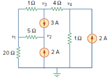
Figure 3.28
For Practice Prob. 3.8.
Want to see the full answer?
Check out a sample textbook solution
Chapter 3 Solutions
Fundamentals of Electric Circuits
Additional Engineering Textbook Solutions
Vector Mechanics for Engineers: Statics and Dynamics
Modern Database Management
Thermodynamics: An Engineering Approach
SURVEY OF OPERATING SYSTEMS
Elementary Surveying: An Introduction To Geomatics (15th Edition)


- S+4 4. Sketch the root locus for L(s) = (s+6) (s+1)2 using rules 1, 2, and 3. For rule 3, you need to find the value of σ and a for the asymptotes. From the root-locus, explain why the closed-loop system is always stable for any choice of the design parameter K in the range 0 < K < ∞o.arrow_forward2. Consider the following system. K(s+3) (s+4) (s+1)(s+2) Check whether the points below are in the root locus. If the point is in the root locus, then also find what the corresponding gain K. i) ii) -2+j3 -2+1√ √ Hint: First find L(s). Next, in L(s) replace s with the value of the point and then express it in polar format r20 using calculator. The point will be in the root locus if and only if = 180° or odd multiple of 180°. When the point is in the root locus, the corresponding gain K is obtained as K ==arrow_forwardsolve and show workarrow_forward
- Design and find values. please solve ASAP (it's for practice before an exma, I don't have time)arrow_forwardCan you show why the answer is that for this question using second order differential equations, instead of laplace transformsarrow_forward2. For each of the following transfer functions, G(s) = Y(s)/U(s), find the differential equation relating the input u(t) to the output y(t). (s+2)(s+3) (a) G(s) = (s+1)(s+4) (s²+0.4s+1.04) (s+3) (b) G(s)= (s2+0.2s+1)(s+2)(s+4)arrow_forward
- Don't use ai to answer I will report you answerarrow_forward5. A schematic diagram of a motor connected to a load by gears is shown. Both the motor and the load are modeled as rotating masses with viscous damping. Find the transfer functions Øm/Tm and ØL/Tm. bm Jm Tm 0m N₂ N₁ OL но JL b₁arrow_forward3. Find the transfer function X2/F of the mechanical system in Figure. Κι www b₁ M₁ K2 www M2 b2 X2 F b3arrow_forward
- S1(t) Es/Ts 0 S3(t) 0 Es/Ts Ts t S2(t) Es/Ts 0 Es/Ts Ts |7|2 S4(t) Es/Ts t Ts t 0 Ts Ts Ts Es/TS 2 1/ Q1(t) 42(t) Ts 1JT 0 t 0 Ts Ts 2 32 FIGURE 7.3 Set of signals and orthonormal functions for Example 7.1. 53(t)=√√Esq₁(t) S4(t)=-√E542(t) t Tsarrow_forward1. For each of the following differential equations, determine the transfer function Y/U. Determine if the transfer function is proper or strictly proper. is not strictly proper, determine the strictly proper part. If it (a) y(3) = -3y(2) - 3y(1) — 2y + u(2) — - (b) y(3)=-3.5y(2) — 3.5y(1) — y +u(3) — 3.5u(2) + 3.5u(¹) + 3uarrow_forward.4. Find the transfer function Ø2/T of the mechanical system in Figure. TG K 02 b₁ b₂ b3arrow_forward
 Introductory Circuit Analysis (13th Edition)Electrical EngineeringISBN:9780133923605Author:Robert L. BoylestadPublisher:PEARSON
 Delmar's Standard Textbook Of ElectricityElectrical EngineeringISBN:9781337900348Author:Stephen L. HermanPublisher:Cengage Learning
 Programmable Logic ControllersElectrical EngineeringISBN:9780073373843Author:Frank D. PetruzellaPublisher:McGraw-Hill Education
 Fundamentals of Electric CircuitsElectrical EngineeringISBN:9780078028229Author:Charles K Alexander, Matthew SadikuPublisher:McGraw-Hill Education
 Electric Circuits. (11th Edition)Electrical EngineeringISBN:9780134746968Author:James W. Nilsson, Susan RiedelPublisher:PEARSON
 Engineering ElectromagneticsElectrical EngineeringISBN:9780078028151Author:Hayt, William H. (william Hart), Jr, BUCK, John A.Publisher:Mcgraw-hill Education,