
Concept explainers
Design a problem to provide better understanding regarding transistors.
Explanation of Solution
Given data:
Refer Figure 3.128 in the textbook for the transistor circuit.
Formula used:
Write the expression for collector current in transistor.
Here,
Calculation:
Let us assume that the value of resistance
The given circuit with the assumed value is shown in Figure 1.
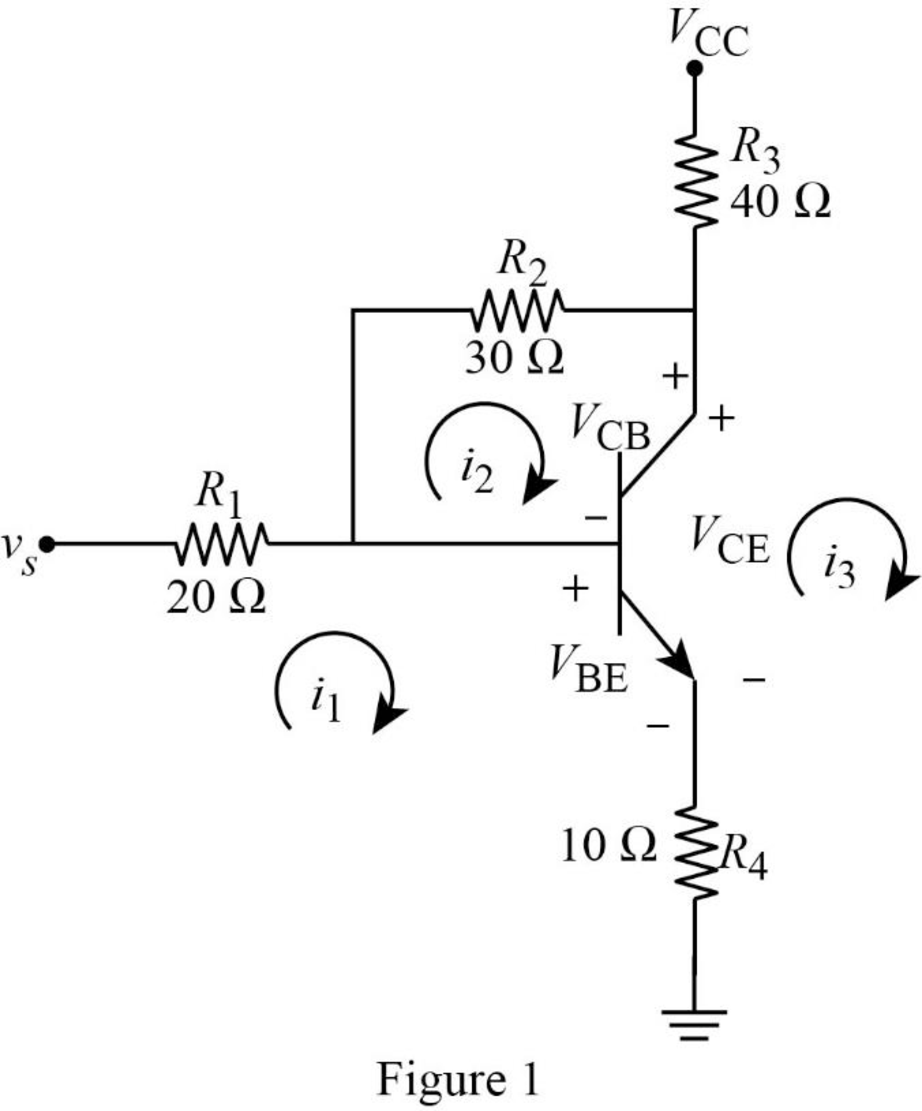
Apply Kirchhoff’s voltage law to loop 1 with current
Substitute
Apply Kirchhoff’s voltage law to loop 2 with current
Apply Kirchhoff’s voltage law to output loop in Figure 1.
Write the constraint equations.
Substitute equations (5) and (6) in (1).
Substitute
Rearrange equation (7).
Substitute equation (9) in (3).
Substitute
Substitute equation (8) in (2).
Substitute equation (10) in (11).
Substitute equation (10) and (12) in (8).
Substitute equation (12) and (13) in (4).
Simplify the equation as follows.
Conclusion:
Therefore, the problem has been designed to provide better understanding regarding transistors.
Want to see more full solutions like this?
Chapter 3 Solutions
Fundamentals of Electric Circuits


- In Experiment PD controller How would the equation become if it were Kp=1 KD=0/0.1/0.5/1/10 s+1 0.02s+1arrow_forwardDon't use ai to answer I will report you answerarrow_forward4. Discussion: GINEE Compare between theoretical combination effect of Kp and KD at first order and second order systems regarding steady-state errors and transient responses with the practical obtained results whenever applying step input signalın Experiment PD controller و المهندسة الكهربائيةarrow_forward
- b C Is 3601116-67 Bre ✓ BIb ≤5K 20k e 0-25K 7. Zo Z Zb B=100, Ble=1Kr Zb=S & Zin = S, Zo=S, AV=Sarrow_forwardDon't use ai to answer I will report you answerarrow_forward4. Discussion: GINEE Compare between theoretical combination effect of Kp and KD at first order and second order systems regarding steady-state errors and transient responses with the practical obtained results whenever applying step input signalın Experiment PI controller و الهندسة الكهربائيةarrow_forward
- همسة 4. Discussion: Compare between theoretical combination effect of Kp, KI and KD at second order systems regarding steady-state errors and transient responses with the practical obtained results whenever applying step input signalln Experiment PID Controllerarrow_forwardHi there! I’m working on some practice questions and would appreciate your help. I’ve uploaded two images: the first contains the initial questions (with the second part also typed out below), and the second image shows the final section of the worksheet. Could you please assist me with these?THE QUESTION NUMBERS ARE IN ORDER. 1b). Suppose the flip-flops are 74F74 devices and the AND gates are 74F08 devices. Let maxtpd,D=9ns, maxtsu,D=3ns, and maxtpd,AND=6ns. What is the maximum clock frequency at which the circuit can operate reliably? 2. Compare serial transmission and parallel transmission and discuss their advantages and disadvantages. 3. Explain briefly how the slave can protect itself from being overwhelmed by the master in I2 4. A hypothetical logic family has the following specifications. VOH=4.6V VIH=4.0V VOL=0.5V…arrow_forwardهمسة 4. Discussion: Compare between theoretical combination effect of Kp, KI and KD at second order systems regarding steady-state errors and transient responses with the practical obtained results whenever applying step input signal in Experiment PI Controllerarrow_forward
 Introductory Circuit Analysis (13th Edition)Electrical EngineeringISBN:9780133923605Author:Robert L. BoylestadPublisher:PEARSON
 Delmar's Standard Textbook Of ElectricityElectrical EngineeringISBN:9781337900348Author:Stephen L. HermanPublisher:Cengage Learning
 Programmable Logic ControllersElectrical EngineeringISBN:9780073373843Author:Frank D. PetruzellaPublisher:McGraw-Hill Education
 Fundamentals of Electric CircuitsElectrical EngineeringISBN:9780078028229Author:Charles K Alexander, Matthew SadikuPublisher:McGraw-Hill Education
 Electric Circuits. (11th Edition)Electrical EngineeringISBN:9780134746968Author:James W. Nilsson, Susan RiedelPublisher:PEARSON
 Engineering ElectromagneticsElectrical EngineeringISBN:9780078028151Author:Hayt, William H. (william Hart), Jr, BUCK, John A.Publisher:Mcgraw-hill Education,