
Concept explainers
Videos
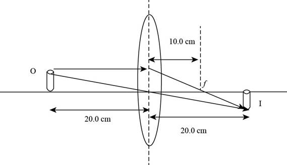
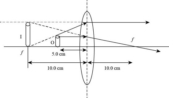
A converging lens has a focal length of 10.0 cm. Construct accurate ray diagrams for object distances of (i) 20.0 cm and (ii) 5.00 cm. (a) From your ray diagrams, determine the location of each image. (b) Is the image real or virtual? (c) Is the image upright or inverted? (d) What is the magnification of the image? (c) Compare your results with the values found algebraically. (f) Comment on difficulties in constructing the graph that could lead to differences between the graphical and algebraic answers.
(i)
To draw: The ray diagram for the given focal lengthy of the lens and the given object distance.
Answer to Problem 26P
Explanation of Solution
Introduction:
In a ray diagram in the case of lens or mirror the image is formed where two at least refracted or reflected rays coincide with each other.
Explanation:
Given info: The position of object is at
The ray diagram is shown in the figure below.

Figure (1)
(ii)
To draw: The ray diagram for the given focal length of the lens and the given object distance.
Answer to Problem 26P
Explanation of Solution
Introduction:
In a ray diagram in the case of lens or mirror the image is formed where two at least refracted or reflected rays coincide with each other.
Explanation:
Given info: The position of object is at
The ray diagram is shown in the figure below.

Figure (2)
(a)
Answer to Problem 26P
Explanation of Solution
From Figure (1), it is evident that the image is formed on the rear end of the lens and the image distance measured is
From Figure (2), the image is formed at
Conclusion:
Therefore, the measured distance for the image for the case when object is at
(b)
Answer to Problem 26P
Explanation of Solution
From Figure (1), it is evident that the image is formed on the rear side and is real and the images formed at the back side of the lens are real.
From Figure (2), the image is formed at
Conclusion:
The images formed by the lens in front of it are virtual and erect and images formed on the back side are real and inverted. Hence, image formed by the object kept at.
(c)
Answer to Problem 26P
Explanation of Solution
From Figure (1), it is evident that the image is formed on the rear side and is real. and
the real images are always inverted
From Figure (2), the image is formed at
The virtual images are always upright.
Conclusion:
Therefore, the images formed by the lens in front of it are virtual and erect and images formed on the back side are real and inverted. Hence, image formed by the object kept at.
(d)
Answer to Problem 26P
Explanation of Solution
Formula to calculate the magnification is
For the object at
For the object at the distance of
Conclusion:
Therefore, for the case of object at
(e)
Answer to Problem 26P
Explanation of Solution
Given Info: The focal length of the give lens is
From Figure (1) the image distance for the object at
For algebraic calculation, the formula for the image distance is,
Here,
Substitute
Form figure (1) the magnification is
Formula to calculate the magnification of the image
Here
Substitute
From figure (2) the image distance is
From equation (4) formula to calculate the image distance is,
Substitute
The image distance is
From equation (6) the formula to calculate the magnification is,
Substitute
From equation (6) and equation (7) it is evident that for the case of object at
From equation (8) and (9) the image distance and magnification is same for the ray diagram and the algebraic case when the object is
Conclusion:
Therefore, the result for the ray diagrams and algebraic calculations are same.
(f)
Answer to Problem 26P
Explanation of Solution
While drawing the graph the possible errors are human hand errors, parallax errors and scale measurement errors.
Human Hand Errors are while making the ray diagrams the rays might not converge with extreme precision. Parallax error/Human eye errors occur due to human eye. Scale errors are during the scale measurement.
Conclusion:
Therefore, the three most common errors that can lead to difficulties in constructing the graph which might lead to change the algebraic and graphical values are human hand errors, parallax errors and Scale errors.
Want to see more full solutions like this?
Chapter 35 Solutions
Physics for Scientists and Engineers


- 8. With the aid of a diagram draw the following electric circuit and use the resistor as the load, (a) Closed circuit (b) Open circuitarrow_forwardLab 8 Part 3 PHET Wave Interface simulation. I am having trouble with this part of the lab.arrow_forwardMick and Rick are twins born on Earth in the year 2175. Rick grows up to be an Earth-bound robotics technician while Mick becomes an intergalactic astronaut. Mick leaves the Earth on his first space mission in the year 2200 and travels, according to his clock, for 10 years at a speed of 0.75c. Unfortunately, at this point in his journey, the structure of his ship undergoes mechanical breakdown and the ship explodes. How old is Rick when his brother dies?arrow_forward
 Principles of Physics: A Calculus-Based TextPhysicsISBN:9781133104261Author:Raymond A. Serway, John W. JewettPublisher:Cengage Learning
 Physics for Scientists and Engineers: Foundations...PhysicsISBN:9781133939146Author:Katz, Debora M.Publisher:Cengage Learning
 University Physics Volume 3PhysicsISBN:9781938168185Author:William Moebs, Jeff SannyPublisher:OpenStax
 Physics for Scientists and EngineersPhysicsISBN:9781337553278Author:Raymond A. Serway, John W. JewettPublisher:Cengage Learning
 Physics for Scientists and Engineers with Modern ...PhysicsISBN:9781337553292Author:Raymond A. Serway, John W. JewettPublisher:Cengage Learning
 Physics for Scientists and Engineers, Technology ...PhysicsISBN:9781305116399Author:Raymond A. Serway, John W. JewettPublisher:Cengage Learning