Concept explainers
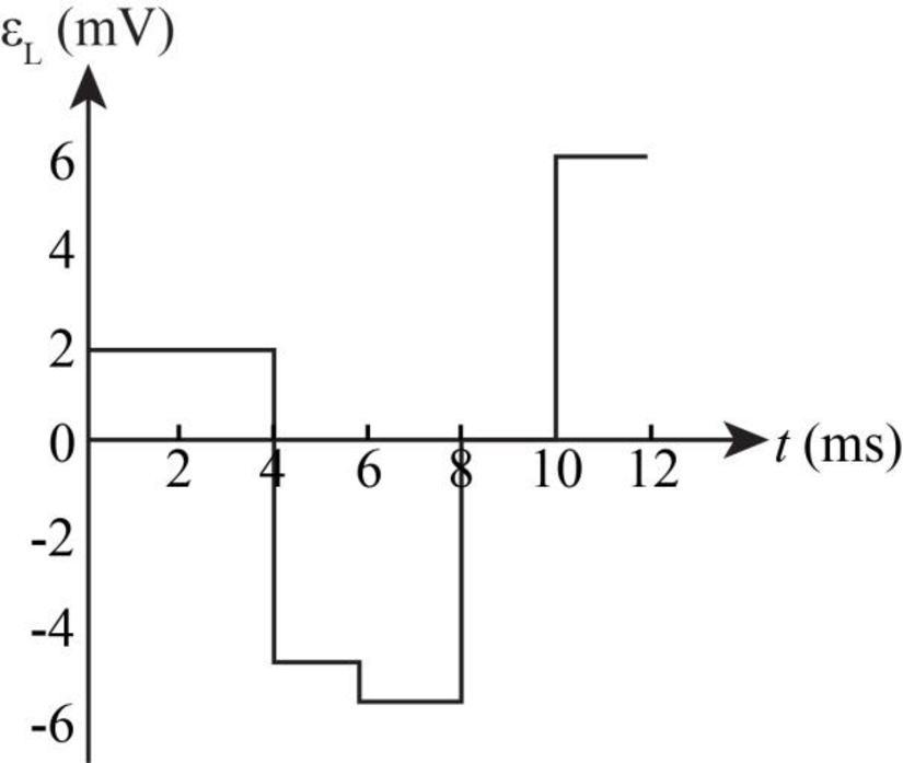
The graph for the self induced emf over the given time interval.
Answer to Problem 14P
The graph for the self induced emf over the given time interval is shown below.
Explanation of Solution
Write the expression to calculate the self induced emf.
Here,
Write the expression to for change in current.
Here,
Substitute
Conclusion:
For the interval
Substitute
For the interval
Substitute
For the interval
Substitute
For the interval
Substitute
For the interval
Substitute
For the interval
Substitute
Therefore, the graph for the self inductance at different time interval is shown in the figure below.

Figure-(1)
Want to see more full solutions like this?
Chapter 32 Solutions
Physics For Scientists And Engineers With Modern Physics, 9th Edition, The Ohio State University


- The rectangular loop of wire shown in the figure (Figure 1) has a mass of 0.18 g per centimeter of length and is pivoted about side ab on a frictionless axis. The current in the wire is 8.5 A in the direction shown. Find the magnitude of the magnetic field parallel to the y-axis that will cause the loop to swing up until its plane makes an angle of 30.0 ∘ with the yz-plane. Find the direction of the magnetic field parallel to the y-axis that will cause the loop to swing up until its plane makes an angle of 30.0 ∘ with the yz-plane.arrow_forwardGive a more general expression for the magnitude of the torque τ. Rewrite the answer found in Part A in terms of the magnitude of the magnetic dipole moment of the current loop m. Define the angle between the vector perpendicular to the plane of the coil and the magnetic field to be ϕ, noting that this angle is the complement of angle θ in Part A. Give your answer in terms of the magnetic moment mm, magnetic field B, and ϕ.arrow_forwardCalculate the electric and magnetic energy densities at thesurface of a 3-mm diameter copper wire carrying a 15-A current. The resistivity ofcopper is 1.68×10⁻⁸ Ω.m.Prob. 18, page 806, Ans: uE= 5.6 10-15 J/m3 uB= 1.6 J/m3arrow_forward
- A 15.8-mW laser puts out a narrow beam 2.0 mm in diameter.Suppose that the beam is in free space. What is the rms value of E in the beam? What isthe rms value of B in the beam?Prob. 28, page 834. Ans: Erms= 1380 V/m, Brms =4.59×10⁻⁶ Tarrow_forwardA 4.5 cm tall object is placed 26 cm in front of a sphericalmirror. It is desired to produce a virtual image that is upright and 3.5 cm tall.(a) What type of mirror should be used, convex, or concave?(b) Where is the image located?(c) What is the focal length of the mirror?(d) What is the radius of curvature of the mirror?Prob. 25, page 861. Ans: (a) convex, (b) di= -20.2 cm, i.e. 20.2 cm behind the mirror,(c) f= -90.55 cm, (d) r= -181.1 cm.arrow_forwardA series RCL circuit contains an inductor with inductance L=3.32 mH, and a generator whose rms voltage is 11.2 V. At a resonant frequencyof 1.25 kHz the average power delivered to the circuit is 26.9 W.(a) Find the value of the capacitance.(b) Find the value of the resistance.(c) What is the power factor of this circuit?Ans: C=4.89 μF, R=4.66 Ω, 1.arrow_forward
- A group of particles is traveling in a magnetic field of unknown magnitude and direction. You observe that a proton moving at 1.70 km/s in the +x-direction experiences a force of 2.06×10⁻¹⁶ N in the +y-direction, and an electron moving at 4.40 km/s in the −z-direction experiences a force of 8.10×10⁻¹⁶ N in the +y-direction. What is the magnitude of the magnetic force on an electron moving in the −y-direction at 3.70 km/s ? What is the direction of this the magnetic force? (in the xz-plane)arrow_forwardA particle with a charge of −5.20 nC is moving in a uniform magnetic field of B =−( 1.22 T )k^. The magnetic force on the particle is measured to be F=−( 3.50×10⁻⁷ N )i^+( 7.60×10⁻⁷ N )j^. Calculate the x component of the velocity of the particle.arrow_forwardIs it possible for average velocity to be negative?a. Yes, in cases when the net displacement is negative.b. Yes, if the body keeps changing its direction during motion.c. No, average velocity describes only magnitude and not the direction of motion.d. No, average velocity describes only the magnitude in the positive direction of motion.arrow_forward
- Tutorial Exercise An air-filled spherical capacitor is constructed with an inner-shell radius of 6.95 cm and an outer-shell radius of 14.5 cm. (a) Calculate the capacitance of the device. (b) What potential difference between the spheres results in a 4.00-μC charge on the capacitor? Part 1 of 4 - Conceptualize Since the separation between the inner and outer shells is much larger than a typical electronic capacitor with separation on the order of 0.1 mm and capacitance in the microfarad range, we expect the capacitance of this spherical configuration to be on the order of picofarads. The potential difference should be sufficiently low to avoid sparking through the air that separates the shells. Part 2 of 4 - Categorize We will calculate the capacitance from the equation for a spherical shell capacitor. We will then calculate the voltage found from Q = CAV.arrow_forwardI need help figuring out how to do part 2 with the information given in part 1 and putting it in to the simulation. ( trying to match the velocity graph from the paper onto the simulation to find the applied force graph) Using this simulation https://phet.colorado.edu/sims/cheerpj/forces-1d/latest/forces-1d.html?simulation=forces-1d.arrow_forwardI need help running the simulation to get the result needed.arrow_forward
 Physics for Scientists and Engineers, Technology ...PhysicsISBN:9781305116399Author:Raymond A. Serway, John W. JewettPublisher:Cengage Learning
 Physics for Scientists and Engineers: Foundations...PhysicsISBN:9781133939146Author:Katz, Debora M.Publisher:Cengage Learning
 Physics for Scientists and EngineersPhysicsISBN:9781337553278Author:Raymond A. Serway, John W. JewettPublisher:Cengage Learning
 Physics for Scientists and Engineers with Modern ...PhysicsISBN:9781337553292Author:Raymond A. Serway, John W. JewettPublisher:Cengage Learning
 Principles of Physics: A Calculus-Based TextPhysicsISBN:9781133104261Author:Raymond A. Serway, John W. JewettPublisher:Cengage Learning