
Videos
An open settling tank shown in the figure contains a liquid suspension. Determine the resultant force acting on the gate and its line of action if the liquid density is 850 kg/m3. The gate is parabolic as sketched, looking straight at the gate.
The Resultant force acting on gate and its line of action.
Answer to Problem 80P
The Resultant force acting on gate is
Explanation of Solution
Given:
Density of liquid is
Draw the cross-sectional view of the gate.
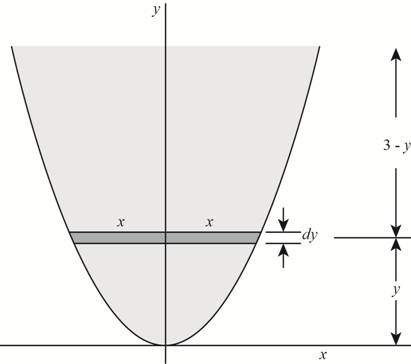
Figure (1)
Write the expression for the curve.
Here, horizontal axis is denoted by the x and vertical axis is denoted by the y.
Write the expression for the vertical distance between the centre of the elemental axis and the x axis.
Here, the vertical distance between the centre of the elemental axis and the x axis is
Write the expression for the area of the elemental strip.
Here, area is
Write the expression for the centre of gravity.
Here, centre of gravity is
Substitute
Draw a view of gate and liquid.
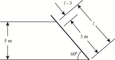
Figure (2)
Write the expression for the length of gate which is in contact with the liquid.
Here, length of the gate is
Write the expression for the centre of gravity of the gate from the free surface.
Here, the mass moment of inertia is
Write the expression for the vertical depth of the centre of gravity of gate from the free surface.
Here, the vertical depth of the centre of gravity of gate from the free surface is
Write the expression for pressure acing on the gate.
Here, pressure acing on the gate is
Write the expression for the area of gate resisting the pressure on the gate.
Here, the area of gate resisting the pressure on the gate is
Write the expression for the resultant force acting on the gate.
Here, the resultant force acting on the gate is
Write the expression for the moment of inertia.
Write the expression for the action of resultant hydrostatic force.
Here, the action of resultant hydrostatic force is
Write the expression for the centre of line of action from the free surface.
Here, the centre of line of action from the free surface is
Write the expression for the centre of location of the force from the bottom.
Here, the centre of location of the force from the bottom is
Calculation:
Substitute
Substitute
Substitute
Substitute
Substitute
Substitute
Substitute
Substitute
Substitute
Draw the diagram for different parameter.
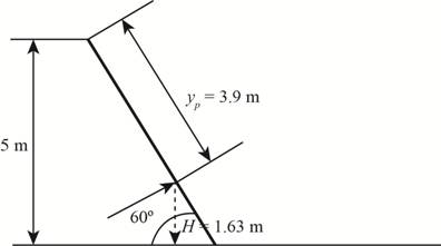
Figure (3)
Substitute
Substitute
Conclusion:
Resultant force acting on gate is
Want to see more full solutions like this?
Chapter 3 Solutions
FLUID MECHANICS FUNDAMENTALS+APPS


- In figure A, the homogeneous rod of constant cross section is attached to unyielding supports. In figure B, a homogeneous bar with a cross-sectional area of 600 mm2 is attached to rigid supports. The bar carries the axial loads P1 = 20 kN and P2 = 60 kN, as shown.1. In figure A, derive the expression that calculates the reaction R1 in terms of P, and the given dimensions.2. In figure B, calculate the reaction (kN) at A.3. In figure B, calculate the maximum axial stress (MPa) in the rod.arrow_forward(Read image)arrow_forward(Read Image)arrow_forward
- M16x2 grade 8.8 bolts No. 25 C1- Q.2. The figure is a cross section of a grade 25 cast-iron pressure vessel. A total of N, M16x2.0 grade 8.8 bolts are to be used to resist a separating force of 160 kN. (a) Determine ks, km, and C. (b) Find the number of bolts required for a load factor of 2 where the bolts may be reused when the joint 19 mm is taken apart. (c) with the number of bolts obtained in (b), determine the realized load factor for overload, the yielding factor of safety, and the separation factor of safety. 19 mmarrow_forwardProblem4. The thin uniform disk of mass m = 1-kg and radius R = 0.1m spins about the bent shaft OG with the angular speed w2 = 20 rad/s. At the same time, the shaft rotates about the z-axis with the angular speed 001 = 10 rad/s. The angle between the bent portion of the shaft and the z-axis is ẞ = 35°. The mass of the shaft is negligible compared to the mass of the disk. a. Find the angular momentum of the disk with respect to point G, based on the axis orientation as shown. Include an MVD in your solution. b. Find the angular momentum of the disk with respect to point O, based on the axis orientation as shown. (Note: O is NOT the center of fixed-point rotation.) c. Find the kinetic energy of the assembly. z R R 002 2R x Answer: H = -0.046ĵ-0.040 kg-m²/sec Ho=-0.146-0.015 kg-m²/sec T 0.518 N-m =arrow_forwardProblem 3. The assembly shown consists of a solid sphere of mass m and the uniform slender rod of the same mass, both of which are welded to the shaft. The assembly is rotating with angular velocity w at a particular moment. Find the angular momentum with respect to point O, in terms of the axes shown. Answer: Ñ。 = ½mc²wcosßsinßĵ + (}{mr²w + 2mb²w + ½ mc²wcos²ß) k 3 m r b 2 C لا marrow_forward
- I have Euler parameters that describe the orientation of N relative to Q, e = -0.7071*n3, e4 = 0.7071. I have Euler parameters that describe the orientation of U relative to N, e = -1/sqrt(3)*n1, e4 = sqrt(2/3). After using euler parameter rule of successive rotations, I get euler parameters that describe the orientation of U relative to Q, e = -0.4082*n1 - 0.4082*n2 - 0.5774*n3. I need euler parameters that describe the orientation of U relative to Q in vector basis of q instead of n. How do I get that?arrow_forwardDescribe at least 4 processes in engineering where control charts are (or should be) appliedarrow_forwardDescribe at least two (2) processes where control charts are (or should be) applied.arrow_forward
 International Edition---engineering Mechanics: St...Mechanical EngineeringISBN:9781305501607Author:Andrew Pytel And Jaan KiusalaasPublisher:CENGAGE L