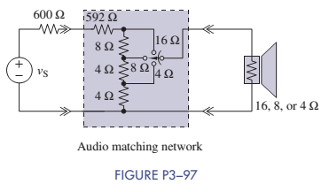
Audio Speaker Resistance-Matching Network
A company is producing an interface network that they claim would result in an
Want to see the full answer?
Check out a sample textbook solutionChapter 3 Solutions
ANALYSIS+DESIGN OF LINEAR CIRCUITS(LL)
- The circuit shown in Figure DP 3-11 is designed to help orange growers protect their crops against frost by sounding an alarm when the temperature falls below freezing. It contains a thermistor that has a resistance Ro=620 N at the temperature To=20 °C=293 °K and ß= 3330 °K. (See problem DP 3-9.) The alarm will sound when the voltage at the - input of the comparator is less than the voltage at the + input. Using voltage division twice, we see that the alarm sounds whenever R2 R4 RT + R2 R3 +R4 Determine values of R2, R3, and R4 that cause the alarm to sound when T = 50 °C 12 V 12 V Thermistor RT R3 Buzzer Comparator RA R2 Figure DP 3-11 Hiarrow_forwardTwo batteries are connected in parallel delivering power to a power resistor. The first battery has an open circuit voltage of 12.6 V and an internal resistance of 0.2 ohm. The second battery has an open circuit voltage of 12.2 V and an internal resistance of 0.3 ohm. Find the maximum power delivered to the load resistance.arrow_forwardWhich of the following statements are correct for the circuit below? Thanks to the capacitors I – C1 and C2, the voltage gain of the circuit increases. II – Capacitors C1 and C2 are coupling capacitors and provide an isolation function between AC and DC voltages in the circuit. Thanks to the III – RE resistor, the voltage gain of the circuit increases. Thanks to the IV – RE resistor, the stability of the circuit increases. The V – C3 Capacitor is a bypass capacitor and prevents the loss of voltage gain. Capacitor VI – C3 is a coupling capacitor and has no effect on the voltage gain in the circuit. VII – As the value of the source internal resistance Rs increases, the voltage gain decreases. VIII – The voltage gain decreases as the value of any RL load to be added to the circuit increasesarrow_forward
- In a house, a circuit often includes multiple electrical outlets which are parallel-connected to a single voltage source. Each of these circuits also contains a 15-A circuit breaker. Design a parallel-connected circuit which shows three electrical outlets con-nected to a voltage source with a circuit breaker. What is the advantage of having out-lets parallel-connected, and why is a circuit breaker connected in series with the voltage source? Why is the circuit breaker considered a necessary safety item in the circuit?arrow_forwardA variable resistive load has a 10-10092 range, and is connected across the load terminals of a circuit. This circuit has a Thevenin voltage and resistance of 150 V and 25 N, respectively. What should be the resistance of the variable resistive load so that it will consume 80% of the max power that this circuit can deliver? (Round-off to two decimal places)arrow_forwardRecreate the circuit in Tinkercad, then measure the currents and voltages across R1, R2, and R3 respectively.arrow_forward
- (b) A resistive position transducer with a resistance of 60002, and a shaft stroke of 5.0 in. is used in the arrangement of Figure Ql(b). Potentiometer R3 R4 is also 60002, and Vr= 6.0V. The initial position to be used as a reference point is such that R1= R2 (i.e., the shaft is at mid-stroke). At the starting of the test, potentiometer R3 and R4 are adjusted so that the bridge is balanced (VE= oV). Assuming that the object being monitored will move at a maximum distance of 1.0 in. toward A. Calculate the new value of VE be?arrow_forwardConsider the circuit shown in below Figure, Find values of the resistances R1 and R2 that cause the voltages v1 and v2 to be v1 = 1 V and v2 = 2 V. 500 2 + + R1 R2 () 5 mA 3 mA V1 V2 6:03 PM 50°F Clear 2/18/2022 P Type here to search Del End F10 PgUp. F11 PgDn F12 PrtScn Home F7 F2 F3 F1 & ) Backspace %23 %24 % 4. 5 7 8. 9. 2 3 W.arrow_forward3-19 When a Skr resistor is connected across a 2 terminal Soure, a carrentd 15 MA IS delivered to the load. When a second 5kr resistor is onnected in parallel with the first, a olal of 20mA is deliered, Find the maximum power available from the source, and for what value of load resistor,arrow_forward
- In the circuit below, the currents through the four resistors are as indicated. Use the junction rule to write the equations representing the relationship between the currents at the point d. (Use the following as necessary: 14, 15, and 16.) 16=14+15 X = 0 &₁ 15 R4 d E₂ =&arrow_forwardTo measure the change in resistance of the gage(s) and indicate the location of the gauge on the beam, construct the Wheatstone bridge circuit. Calculate the Wheatstone bridge output if the gauge indicates a strain of 4000.then,Evaluate how can the number of strain gauges affects your measurement result. Justify your response with a calculation and a diagram showing the gage's placement on the beam.arrow_forwardWhat is the zener current for the circuit shown? Please choose one: a. 6.0 mA b. 9.0 mA c. 7.5 mA D. 3.0 mAarrow_forward
- Introductory Circuit Analysis (13th Edition)Electrical EngineeringISBN:9780133923605Author:Robert L. BoylestadPublisher:PEARSONDelmar's Standard Textbook Of ElectricityElectrical EngineeringISBN:9781337900348Author:Stephen L. HermanPublisher:Cengage LearningProgrammable Logic ControllersElectrical EngineeringISBN:9780073373843Author:Frank D. PetruzellaPublisher:McGraw-Hill Education
- Fundamentals of Electric CircuitsElectrical EngineeringISBN:9780078028229Author:Charles K Alexander, Matthew SadikuPublisher:McGraw-Hill EducationElectric Circuits. (11th Edition)Electrical EngineeringISBN:9780134746968Author:James W. Nilsson, Susan RiedelPublisher:PEARSONEngineering ElectromagneticsElectrical EngineeringISBN:9780078028151Author:Hayt, William H. (william Hart), Jr, BUCK, John A.Publisher:Mcgraw-hill Education,