
ANALYSIS+DESIGN OF LINEAR CIRCUITS(LL)
8th Edition
ISBN: 9781119235385
Author: Thomas
Publisher: WILEY
expand_more
expand_more
format_list_bulleted
Concept explainers
Videos
Textbook Question
Chapter 3, Problem 3.55P
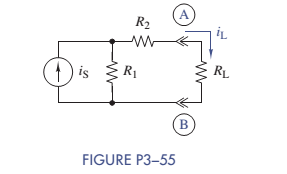
- Find the Thévenin or Norton equivalent circuit seen by
- Use the equivalent circuit found in part (a) to find
- Check your answer to part (b) using current division.
Expert Solution & Answer
Want to see the full answer?
Check out a sample textbook solution
Students have asked these similar questions
Find Eigenvalues and Eigenvectors for the following matrices:
[5 -6 1
A = 1
1
0
3
0
1
Use Gauss-Jordan Elimination method to solve the following system:
4x1+5x2 + x3 = 2
x1-2x2-3x3 = 7
3x1 x2 2x3 = 1.
-
3. As the audio frequency of Fig. 11-7 goes down, what components of Fig.
12-4 must be modified for normal operation?
OD
C₂ 100
HF
R₁ 300
Re 300
ww
100A
R
8
Voc
Rz
10k
reset
output 3
R7
8
Voc
3
reset
output
Z
discharge
VR₁
5k
2
trigger
2 trigger
7
discharge
R 3
1k
5
control
voltage
threshold 6
5 control
voltage
6
threshold
GND
Rs
2k
C.
C.
100
GND
Uz LM555 1
Ce
0.01
U, LM555
0.01
8.01.4
PRO
Fig. 11-7
Audio lutput
Pulse width modulator
R4 1k
ww
C7
Re 1k
ww
R7 100
VR
50k
10μ
Ra
R10
C₁.
R1
3.9k
3.9k
0.14 100k
TO
w
Rs 51
82
3
H
10
Carrier
U₁
Ca
Input
A741
2.2
Us
MC1496
PWM signal
input
R2
0.1100k
Uz
A741
41
Cs
1
Re
10k
VR2
50k
VR3
100k
14
12
C3.
3% +
Ce
0.1
10μ
5
1A
HH
C
+12V
0.1
O PWM
Output
C
0.02-
R
100k +12 V
Demodulated
output
6
Ca
0.33
w
R
10k
R12
100k
ww 31
о
+
4A741
-12 V
Fig. 12-4 PWM demodulator
C
1500p
Chapter 3 Solutions
ANALYSIS+DESIGN OF LINEAR CIRCUITS(LL)
Ch. 3 - Formulate node-voltage equations for the circuit...Ch. 3 - (a) Formulate node-voltage equations for the...Ch. 3 - (a) Formulate node-voltage equations for the...Ch. 3 - Formulate node-voltage equations for the circuit...Ch. 3 - (a) Formulate node-voltage equations for the...Ch. 3 - Choose a ground wisely and formulate node-voltage...Ch. 3 - The following are a set of node-voltage equations;...Ch. 3 - Choose a ground wisely and formulate node-voltage...Ch. 3 - Formulate node-voltage equations for the circuit...Ch. 3 - Formulate node-voltage equations for the circuit...
Ch. 3 - (a) Formulate mesh-current equations for the...Ch. 3 - (a) Formulate mesh-current equations for the...Ch. 3 - (a) Formulate mesh-current equations for the...Ch. 3 - Prob. 3.16PCh. 3 - Formulate mesh-current equations for the circuit...Ch. 3 - For the circuit of figure P3-19 solve for iA,iB,...Ch. 3 - Formulate mesh-current equations for the circuit...Ch. 3 - The circuit in Figure P3-21 seems to require two...Ch. 3 - Formulate mesh-current equations for the circuit...Ch. 3 - Use simple engineering intuition to find the input...Ch. 3 - In Figure P3-24 all of the resistors are 1k and...Ch. 3 - Use Figure P3-24 and MATLAB to solve the following...Ch. 3 - Formulate mesh-current equations for the circuit...Ch. 3 - Find vO for the block diagram shown in figure...Ch. 3 - Design a voltage-divider circuit that will realize...Ch. 3 - Design a current-divider circuit that will realize...Ch. 3 - Using a single resistor, design a circuit that...Ch. 3 - Find the proportionality constant K=vO/vS for the...Ch. 3 - Find the proportionality constant K=iO/vS for the...Ch. 3 - Find the proportionality constant K=vO/iS for the...Ch. 3 - Find the proportionality constant K=iO/iS for the...Ch. 3 - Find the proportionality constant K=vO/vS for the...Ch. 3 - Use the unit output method to find K and vO in...Ch. 3 - Use the unit output method to find K and vO in...Ch. 3 - Use the unit output method to find K in Figure...Ch. 3 - Use the superposition principle to find vO in...Ch. 3 - Use the superposition principle to find vO in...Ch. 3 - Use the superposition principle to find vO in...Ch. 3 - (a) Use the superposition principle to find vO in...Ch. 3 - A linear circuit containing two sources drives a...Ch. 3 - A block diagram of a linear circuit is shown in...Ch. 3 - A certain linear circuit has four input voltages...Ch. 3 - When the current source is turned off in the...Ch. 3 - For the circuit in Figure P3—51, find the Thévenin...Ch. 3 - For the circuit in Figure P3—52, find the Thévenin...Ch. 3 - For the circuit of Figure P3—53, find the Thévenin...Ch. 3 - Find the Thévenin or Norton equivalent circuit...Ch. 3 - Find the Thévenin or Norton equivalent circuit...Ch. 3 - Find the Thévenin equivalent circuit seen by RL in...Ch. 3 - Find the Norton equivalent seen by RL in Figure...Ch. 3 - You need to determine the Thévenin equivalent...Ch. 3 - Find the Thévenin equivalent seen by RL in figure...Ch. 3 - The purpose of this problem is to use Thévenin...Ch. 3 - The circuit in Figure P3-62 was solved earlier...Ch. 3 - Assume that Figure P3-63 represents a model of the...Ch. 3 - The iv characteristic of the active circuit...Ch. 3 - You have successfully completed the first course...Ch. 3 - The Thévenin equivalent parameters of a practical...Ch. 3 - Use a sequence of source transformations to find...Ch. 3 - The circuit in Figure P3-68 provides power to a...Ch. 3 - A nonlinear resistor is connected across a...Ch. 3 - Prob. 3.71PCh. 3 - Find the Norton equivalent seen by RL in Figure...Ch. 3 - Find the Thévenin equivalent seen by RL in Figure...Ch. 3 - Find the Thévenin equivalent seen by RL in Figure...Ch. 3 - For the circuit of Figure P3-75, find the value of...Ch. 3 - For the circuit of Figure P3-76, find the value of...Ch. 3 - The resistance R in Figure P3-77 is adjusted until...Ch. 3 - When a 5-k resistor is connected across a...Ch. 3 - Find the value of R in the circuit of Figure P3-79...Ch. 3 - For the circuit of Figure P3-80, find the value of...Ch. 3 - A 1-k load needs 10 mA to operate correctly....Ch. 3 - A practical source delivers 25 mA to a load. The...Ch. 3 - A 10-V source is shown in Figure P3-83 that is...Ch. 3 - (a)Select RL and design an interface circuit for...Ch. 3 - The source in Figure P3-85 has a 100-mA output...Ch. 3 - Figure P3-86 shows an interface circuit connecting...Ch. 3 - Prob. 3.87PCh. 3 - In this problem, you will design two interface...Ch. 3 - Two teams are competing to design the interface...Ch. 3 - The bridge-T attenuation pad shown in FigureP3-90...Ch. 3 - Design two interface circuits in Figure P3-91 so...Ch. 3 - Design the interface circuit in Figure P3-91 so...Ch. 3 - Design the interface circuit in Figure P3-93 so...Ch. 3 - It is claimed that both interface circuits in...Ch. 3 - Audio Speaker Resistance-Matching Network A...Ch. 3 - Interface Circuit Design Using no more than three...Ch. 3 - Battery Design A satellite requires a battery with...Ch. 3 - Design Interface Competition The output of a...Ch. 3 - Prob. 3.106IP
Knowledge Booster


Learn more about
Need a deep-dive on the concept behind this application? Look no further. Learn more about this topic, electrical-engineering and related others by exploring similar questions and additional content below.Similar questions
- DUC 1. In Fig. 12-4, what are the functions of the VR1 and VR2? 2. In Fig. 12-4, what is the function of the VR3? VR₁ 50k C₁ R1 0.1 100k Carrier Input U₁ A741 PWM signal input R41k www Re 1k w C7 ± 10μT R7 100 ww =L H C4 2.2 H W82 Rs 51 3 10 U3 MC1496 C2 R2 U2 A741 22 0.1 100k VR2 50k VR3 100kr 14 C3 10μ 1k 0.1 4 5 6 12 m Re 10k R9 R102 3.9k 3.9k HHI C10 0.1 -0 +12V C11 R 0.02 100k +12 V Demodulated output C R11 R12 A741 0.33 10k 100k -12 V Ca 1μ C12 1500p PRODUC Fig. 12-4 PWM demodulator PRODUCTSarrow_forward10.37 Use mesh analysis to find currents I₁, I2, and I3 in the circuit of Fig. 10.82. ML 120-90° V 120 -30° V Figure 10.82 For Prob. 10.37. N N Z=80-135arrow_forward3. Find the phasor current I。 in the circuit shown below. Be aware of the direction markings. (15 pts) 1052 I 5057 ①520 Amps 2012 j5052arrow_forward
- 10.93 Figure 10.135 shows a Colpitts oscillator. Show that the ed oscillation frequency is 1 fo= 2π √√LCT where CTC₁C2/(C₁ + C₂). Assume R; >>> R₁ + Rf ww Vo L m C₂ C₁ 5 Xci Figure 10.135 A Colpitts oscillator; for Prob. 10.93. (Hint: Set the imaginary part of the impedance in the feedback circuit equal to zero.)arrow_forwardDetermine (a) the average and (b) rms values of the periodiccurrent waveform shown in Fig. P8.3.arrow_forward10.68 Find the Thevenin equivalent at terminals a-b in the circuit of Fig. 10.111. ML 6 sin 10t V 492 Figure 10.111 For Prob. 10.68. 5913 + 410 + -2 F 20 1H Vo obarrow_forward
- 10.79 For the op amp circuit in Fig. 10.122, obtain Vo. 5 cos 10³t V(+ Figure 10.122 For Prob. 10.79. 10 ΚΩ www 20 ΚΩ www 0.1 µF 40 ΚΩ 0.2 μFarrow_forward10.19 Obtain V, in Fig. 10.68 using nodal analysis. # ML ΖΩ j20 m 12/0° V 492 (+ ww www ' < ་ + V -j4 0.2V Figure 10.68 For Prob. 10.19.arrow_forward10.47 Determine i, in the circuit of Fig. 10.92, using the superposition principle. ML 10 sin(t -30°) V 1Ω www Figure 10.92 For Prob. 10.47. 96 F 202 www 24 V +) 2 H m io 2 cos 3t www 42arrow_forward
- 10.53 Use the concept of source transformation to find V, in the circuit of Fig. 10.97. 492 www -j30 j40 m + 20/0° V(+ j20 ΖΩ www -120 V ° Figure 10.97 For Prob. 10.53.arrow_forward2. Given you have a real valued signal with the following single sided baseband signal spectrum: ↑ ❘m(f)| A f=0 500 750 Sketch the frequency domain of |X(f)| given: a. x1(t) =m(t)cos(2**5000*) b. x2(t)=m(t)cos(2**600) Frequency (Hz)arrow_forwardwhat is deference between full Adder and Half?arrow_forward
arrow_back_ios
SEE MORE QUESTIONS
arrow_forward_ios
Recommended textbooks for you
 Introductory Circuit Analysis (13th Edition)Electrical EngineeringISBN:9780133923605Author:Robert L. BoylestadPublisher:PEARSON
 Delmar's Standard Textbook Of ElectricityElectrical EngineeringISBN:9781337900348Author:Stephen L. HermanPublisher:Cengage Learning
 Programmable Logic ControllersElectrical EngineeringISBN:9780073373843Author:Frank D. PetruzellaPublisher:McGraw-Hill Education
 Fundamentals of Electric CircuitsElectrical EngineeringISBN:9780078028229Author:Charles K Alexander, Matthew SadikuPublisher:McGraw-Hill Education
 Electric Circuits. (11th Edition)Electrical EngineeringISBN:9780134746968Author:James W. Nilsson, Susan RiedelPublisher:PEARSON
 Engineering ElectromagneticsElectrical EngineeringISBN:9780078028151Author:Hayt, William H. (william Hart), Jr, BUCK, John A.Publisher:Mcgraw-hill Education,
Introductory Circuit Analysis (13th Edition)
Electrical Engineering
ISBN:9780133923605
Author:Robert L. Boylestad
Publisher:PEARSON
Delmar's Standard Textbook Of Electricity
Electrical Engineering
ISBN:9781337900348
Author:Stephen L. Herman
Publisher:Cengage Learning
Programmable Logic Controllers
Electrical Engineering
ISBN:9780073373843
Author:Frank D. Petruzella
Publisher:McGraw-Hill Education
Fundamentals of Electric Circuits
Electrical Engineering
ISBN:9780078028229
Author:Charles K Alexander, Matthew Sadiku
Publisher:McGraw-Hill Education
Electric Circuits. (11th Edition)
Electrical Engineering
ISBN:9780134746968
Author:James W. Nilsson, Susan Riedel
Publisher:PEARSON
Engineering Electromagnetics
Electrical Engineering
ISBN:9780078028151
Author:Hayt, William H. (william Hart), Jr, BUCK, John A.
Publisher:Mcgraw-hill Education,
Thevenin's Theorem; Author: Neso Academy;https://www.youtube.com/watch?v=veAFVTIpKyM;License: Standard YouTube License, CC-BY