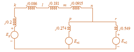
Figure 3.39 shows a oneline diagram of a system in which the three-phase generator is rated 300 MVA, 20 kV with a subtransient reactance of 0.2 per unit and with its neutral grounded through a 0.4 -Ω reactor. The transmission line is 64km long with a cries reactance of 0.5 -Ω/km . The three-phase transformer T 1 is rated 35 0 MVA . 230/ 2 0 kV with a leakage reactance of 0.1 per unit. Transformer T 2 is composed of three single-phase transformers, each rated 100 MVA, 127 / 13 . 2 kV with a leakage reactance of 0.1 per unit. Two 13 . 2 − kV motors M 1 and M 2 with a subtransient reactance of 0.2 per unit for each motor represent the load. M 1 has a rated input of 200 MVA with its neutral grounded through a 0.4 -Ω current-limiting reactor, M 2 has a rated input of 100 MVA with its neutral not connected to ground. Neglect phase shifts associated with the transformers. Choose the generator rating as base in the generator circuit and draw the positive-sequence reactance diagram showing all reactances in per unit.
Figure 3.39 shows a oneline diagram of a system in which the three-phase generator is rated 300 MVA, 20 kV with a subtransient reactance of 0.2 per unit and with its neutral grounded through a 0.4 -Ω reactor. The transmission line is 64km long with a cries reactance of 0.5 -Ω/km . The three-phase transformer T 1 is rated 35 0 MVA . 230/ 2 0 kV with a leakage reactance of 0.1 per unit. Transformer T 2 is composed of three single-phase transformers, each rated 100 MVA, 127 / 13 . 2 kV with a leakage reactance of 0.1 per unit. Two 13 . 2 − kV motors M 1 and M 2 with a subtransient reactance of 0.2 per unit for each motor represent the load. M 1 has a rated input of 200 MVA with its neutral grounded through a 0.4 -Ω current-limiting reactor, M 2 has a rated input of 100 MVA with its neutral not connected to ground. Neglect phase shifts associated with the transformers. Choose the generator rating as base in the generator circuit and draw the positive-sequence reactance diagram showing all reactances in per unit.
Figure 3.39 shows a oneline diagram of a system in which the three-phase generator is rated 300 MVA, 20 kV with a subtransient reactance of 0.2 per unit and with its neutral grounded through a
0.4
-Ω
reactor. The transmission line is 64km long with a cries reactance of
0.5
-Ω/km
. The three-phase transformer
T
1
is rated
35
0
MVA
.
230/
2
0
kV
with a leakage reactance of 0.1 per unit. Transformer
T
2
is composed of three single-phase transformers, each rated 100 MVA,
127
/
13
.
2
kV
with a leakage reactance of 0.1 per unit. Two
13
.
2
−
kV
motors
M
1
and
M
2
with a subtransient reactance of 0.2 per unit for each motor represent the load.
M
1
has a rated input of 200 MVA with its neutral grounded through a
0.4
-Ω
current-limiting reactor,
M
2
has a rated input of 100 MVA with its neutral not connected to ground. Neglect phase shifts associated with the transformers. Choose the generator rating as base in the generator circuit and draw the positive-sequence reactance diagram showing all reactances in per unit.
Only expert should attempt this questions, handwritten solution only
Please show formula used and steps as I will study them
Question One
R
C
ww
(t)T
Figure 2: R-C Circuit
A series R-C circuit in figure 2, has a step input voltage applied to it. Use Laplace transforms
to determine expressions for
(a) Current, i(t) flowing in the circuit, given that when t = Os, i=0A [12 marks]
(b) Use the expression obtained in (a), calculate the current i(t) flowing in the circuit,
when V = 15volts, R = 50, C=1F, t = 1sec
[2 marks]
Need a deep-dive on the concept behind this application? Look no further. Learn more about this topic, electrical-engineering and related others by exploring similar questions and additional content below.


 Power System Analysis and Design (MindTap Course ...Electrical EngineeringISBN:9781305632134Author:J. Duncan Glover, Thomas Overbye, Mulukutla S. SarmaPublisher:Cengage Learning