Consider a single-phase electric system shown in Figure 3.33. Transformers are rated as follows: X − Y 15 MVA , 13 . 8 / 138 kV , leakage reactance 10 % Y − Z 15 MVA , 138 / 69 kV , leakage reactance 8 % With the base in circuit Y chosen as 15MVA , 138 kV determine the per-unit impedance of the 500 Ω resistive load in circuit Z, referred to circuits Z, Y, and X. Neglecting magnetizing currents, transformer resistances, and line impedances, draw the impedance diagram in per unit.
Consider a single-phase electric system shown in Figure 3.33. Transformers are rated as follows: X − Y 15 MVA , 13 . 8 / 138 kV , leakage reactance 10 % Y − Z 15 MVA , 138 / 69 kV , leakage reactance 8 % With the base in circuit Y chosen as 15MVA , 138 kV determine the per-unit impedance of the 500 Ω resistive load in circuit Z, referred to circuits Z, Y, and X. Neglecting magnetizing currents, transformer resistances, and line impedances, draw the impedance diagram in per unit.
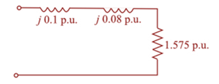
Solution Summary: The author illustrates a per-unit impedance diagram for the transformer X-Y and Transformer Y-Z circuits.
Consider a single-phase electric system shown in Figure 3.33. Transformers are rated as follows:
X
−
Y 15 MVA
,
13
.
8
/
138
kV
,
leakage reactance
10
%
Y
−
Z 15 MVA
,
138
/
69
kV
,
leakage reactance
8
%
With the base in circuit Y chosen as
15MVA
,
138 kV
determine the per-unit impedance of the
500
Ω
resistive load in circuit Z, referred to circuits Z, Y, and X. Neglecting magnetizing currents, transformer resistances, and line impedances, draw the impedance diagram in per unit.
I need help checking if its correct
-E1 + VR1 + VR4 – E2 + VR3 = 0 -------> Loop 1 (a)
R1(I1) + R4(I1 – I2) + R3(I1) = E1 + E2 ------> Loop 1 (b)
R1(I1) + R4(I1) - R4(I2) + R3(I1) = E1 + E2 ------> Loop 1 (c)
(R1 + R3 + R4) (I1) - R4(I2) = E1 + E2 ------> Loop 1 (d)
Now that we have loop 1 equation will procced on finding the equation of I2 current loop. However, a reminder that because we are going in a clockwise direction, it goes against the direction of the current. As such we will get an equation for the matrix that will be:
E2 – VR4 – VR2 + E3 = 0 ------> Loop 2 (a)
-R4(I2 – I1) -R2(I2) = -E2 – E3 ------> Loop 2 (b)
-R4(I2) + R4(I1) - R2(I2) = -E2 – E3 -----> Loop 2 (c)
R4(I1) – (R4 + R2)(I2) = -E2 – E3 -----> Loop 2 (d)
These two equations will be implemented to the matrix formula I = inv(A) * b
R11 R12
(R1 + R3 + R4)
-R4
-R4
R4 + R2
10.2 For each of the following groups of sources, determineif the three sources constitute a balanced source, and if it is,determine if it has a positive or negative phase sequence.(a) va(t) = 169.7cos(377t +15◦) Vvb(t) = 169.7cos(377t −105◦) Vvc(t) = 169.7sin(377t −135◦) V(b) va(t) = 311cos(wt −12◦) Vvb(t) = 311cos(wt +108◦) Vvc(t) = 311cos(wt +228◦) V(c) V1 = 140 −140◦ VV2 = 114 −20◦ VV3 = 124 100◦ V
Apply single-phase equivalency to determine the linecurrents in the Y-D network shown in Fig. P10.13. The loadimpedances are Zab = Zbc = Zca = (25+ j5) W
Need a deep-dive on the concept behind this application? Look no further. Learn more about this topic, electrical-engineering and related others by exploring similar questions and additional content below.


 Power System Analysis and Design (MindTap Course ...Electrical EngineeringISBN:9781305632134Author:J. Duncan Glover, Thomas Overbye, Mulukutla S. SarmaPublisher:Cengage Learning