
EBK POWER SYSTEM ANALYSIS AND DESIGN
6th Edition
ISBN: 9781305886957
Author: Glover
Publisher: CENGAGE LEARNING - CONSIGNMENT
expand_more
expand_more
format_list_bulleted
Concept explainers
Videos
Textbook Question
Chapter 3, Problem 3.32P
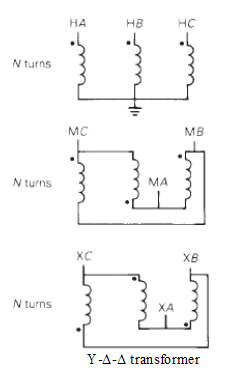
Determine the positive- and negative-sequence phase shifts for the three- phase transformers shown in Figure 3.36.
Expert Solution & Answer

Trending nowThis is a popular solution!

Students have asked these similar questions
Select a short-circuit withstanding (1-second short circuit length) cable for Feeder 1 in
Figure 1. Values for cables are given in Table 1. The voltage of the supplying network is
now 115 kV and the short-circuit power of the supplying network is 2000 MVA.
Table 1. Technical information of 3-phase cables (10 kV and 20 kV)
Product's name
EA-number
Structural information
20KV
20KV
20 KV
0624250
0624252
0624253
0624254
AHKAMK-W AHKAMKW AHKAMKWAHKAMKW AHKAMKW AHKAMKW AHKAMKW
3x50Al+35Cu 3x95 Al. 35Cu 3x120Al. 35Cu 3x150Al+35Cu 3x185Al+35Cu 3x240A1+70 Cu 3x300Al+70Cu
20kV
20kV 20 kV (8) 20KV
0624255
0624257
0624256
Diameter of conductor
Diameter of out-most circle
Cable's outer diameter
Mass
Delivery information
Standard length
Delivery reel
mm
8.0
11.3
12.7
14.1
15.7
18.1
20.3
mm
28
32
34
35
37
40
43
mm
64
71
74
76
80
89
94
aluminium
kg/km
510
910
1100
1350
1650
2200
2700
сорраг
kg/km
305
305
305
305
305
600
600
cable
kg/km
2350
3100
3450
3800
4300
5500
6250
E
500
500
500
500
500
500
500…
A three-phase 20 kV medium-voltage line is 10 km. Resistance is 0.252 2/km and reactance
is 0.128 92/km (inductive). Voltage at the beginning of line is 21.0 kV. At the end of the line
is loading P = 2.5 MW with power factor 0.92ind. Draw 1-phase equivalent diagram and
calculate line voltage at the end the of line, active and reactive power at the beginning of the
line and power losses of the line.
A three-phase 20 kV medium-voltage line is 10 km. Resistance is 0.365 2/km and
reactance is 0.363 2/km (inductive). Voltage at the beginning of line is 20.5 kV. At the
end of the line is loading P= 800 kW with power factor 0.95ind. Draw 1-phase equivalent
diagram and calculate load current, line voltage at the end the of line, voltage drop and
power losses of the line.
Chapter 3 Solutions
EBK POWER SYSTEM ANALYSIS AND DESIGN
Ch. 3 - The Ohms law for the magnetic circuit states that...Ch. 3 - For an ideal transformer, the efficiency is (a) 0...Ch. 3 - For an ideal 2-winding transformer, the...Ch. 3 - An ideal transformer has no real or reactive power...Ch. 3 - For an ideal 2-winding transformer, an impedance...Ch. 3 - Consider Figure 3.4. For an ideal phase-shifting...Ch. 3 - Consider Figure 3.5. Match the following, those on...Ch. 3 - The units of admittance, conductance, and...Ch. 3 - Match the following: (i) Hysteresis loss (a) Can...Ch. 3 - For large power transformers rated more than 500...
Ch. 3 - For a short-circuit test on a 2-winding...Ch. 3 - The per-unit quantity is always dimensionless. (a)...Ch. 3 - Consider the adopted per-unit system for the...Ch. 3 - The ideal transformer windings are eliminated from...Ch. 3 - To convert a per-unit impedance from old to new...Ch. 3 - In developing per-unit circuits of systems such as...Ch. 3 - Prob. 3.17MCQCh. 3 - Prob. 3.18MCQCh. 3 - With the American Standard notation, in either a...Ch. 3 - Prob. 3.20MCQCh. 3 - In order to avoid difficulties with third-harmonic...Ch. 3 - Does an open connection permit balanced...Ch. 3 - Does an open- operation, the kVA rating compared...Ch. 3 - It is stated that (i) balanced three-phase...Ch. 3 - In developing per-unit equivalent circuits for...Ch. 3 - In per-unit equivalent circuits of practical...Ch. 3 - Prob. 3.27MCQCh. 3 - Prob. 3.28MCQCh. 3 - For developing per-unit equivalent circuits of...Ch. 3 - Prob. 3.30MCQCh. 3 - Prob. 3.31MCQCh. 3 - Prob. 3.32MCQCh. 3 - The direct electrical connection of the windings...Ch. 3 - Consider Figure 3.25 of the text for a transformer...Ch. 3 - (a) An ideal single-phase two-winding transformer...Ch. 3 - An ideal transformer with N1=1000andN2=250 is...Ch. 3 - Consider an ideal transformer with...Ch. 3 - A single-phase 100-kVA,2400/240-volt,60-Hz...Ch. 3 - Prob. 3.5PCh. 3 - Prob. 3.6PCh. 3 - Consider a source of voltage v(t)=102sin(2t)V,...Ch. 3 - Prob. 3.8PCh. 3 - Prob. 3.9PCh. 3 - A single-phase step-down transformer is rated...Ch. 3 - For the transformer in Problem 3.10. The...Ch. 3 - Prob. 3.12PCh. 3 - A single-phase 50-kVA,2400/240-volt,60-Hz...Ch. 3 - A single-phase 50-kVA,2400/240-volt,60-Hz...Ch. 3 - Rework Problem 3.14 if the transformer is...Ch. 3 - A single-phase, 50-kVA,2400/240-V,60-Hz...Ch. 3 - The transformer of Problem 3.16 is supplying a...Ch. 3 - Using the transformer ratings as base quantities,...Ch. 3 - Using the transformer ratings as base quantities....Ch. 3 - Using base values of 20 kVA and 115 volts in zone...Ch. 3 - Prob. 3.21PCh. 3 - A balanced Y-connected voltage source with...Ch. 3 - Figure 3.32 shows the oneline diagram of a...Ch. 3 - For Problem 3.18, the motor operates at full load,...Ch. 3 - Consider a single-phase electric system shown in...Ch. 3 - A bank of three single-phase transformers, each...Ch. 3 - A three-phase transformer is rated...Ch. 3 - For the system shown in Figure 3.34. draw an...Ch. 3 - Consider three ideal single-phase transformers...Ch. 3 - Reconsider Problem 3.29. If Va,VbandVc are a...Ch. 3 - Prob. 3.31PCh. 3 - Determine the positive- and negative-sequence...Ch. 3 - Consider the three single-phase two-winding...Ch. 3 - Three single-phase, two-winding transformers, each...Ch. 3 - Consider a bank of this single-phase two-winding...Ch. 3 - Three single-phase two-winding transformers, each...Ch. 3 - Three single-phase two-winding transformers, each...Ch. 3 - Consider a three-phase generator rated...Ch. 3 - The leakage reactance of a three-phase,...Ch. 3 - Prob. 3.40PCh. 3 - Consider the single-line diagram of the power...Ch. 3 - For the power system in Problem 3.41, the...Ch. 3 - Three single-phase transformers, each rated...Ch. 3 - A 130-MVA,13.2-kV three-phase generator, which has...Ch. 3 - Figure 3.39 shows a oneline diagram of a system in...Ch. 3 - The motors M1andM2 of Problem 3.45 have inputs of...Ch. 3 - Consider the oneline diagram shown in Figure 3.40....Ch. 3 - With the same transformer banks as in Problem...Ch. 3 - Consider the single-Line diagram of a power system...Ch. 3 - A single-phase three-winding transformer has the...Ch. 3 - The ratings of a three-phase three-winding...Ch. 3 - Prob. 3.52PCh. 3 - The ratings of a three-phase, three-winding...Ch. 3 - An infinite bus, which is a constant voltage...Ch. 3 - A single-phase l0-kVA,2300/230-volt,60-Hz...Ch. 3 - Three single-phase two-winding transformers, each...Ch. 3 - A two-winding single-phase transformer rated...Ch. 3 - A single-phase two-winding transformer rated...Ch. 3 - Prob. 3.59PCh. 3 - PowerWorid Simulator case Problem 3_60 duplicates...Ch. 3 - Rework Example 3.12 for a+10 tap, providing a 10...Ch. 3 - A 23/230-kV step-up transformer feeds a...Ch. 3 - The per-unit equivalent circuit of two...Ch. 3 - Reconsider Problem 3.64 with the change that now...Ch. 3 - What are the advantages of correctly specifying a...Ch. 3 - Why is it important to reduce the moisture within...Ch. 3 - What should be the focus of transformer preventive...
Knowledge Booster


Learn more about
Need a deep-dive on the concept behind this application? Look no further. Learn more about this topic, electrical-engineering and related others by exploring similar questions and additional content below.Similar questions
- 6. Answer the following questions. Take help from ChatGPT to answer these questions (if you need). Write the answers briefly using your own words with no more than two sentences, and make sure you check whether ChatGPT is giving you the appropriate answers in our context. A) What is a model in our context? B) What is an LTI system? C) What are the three forms of model we have used in the class so far to represent an LTI system? Among the above three forms, which forms can still be used to represent a nonlinear system?arrow_forward5. Consider the following block diagram of a system in the Figure 4. Y₁(s) G₁ G2. R(s) C(s) Y₂(s) G3 G4 Figure 4 The models of the blocks G1, G2, G3 and G4 are represented by a differential equation, transfer function, state-space form, and impulse response as the followings. dy1 G₁: +2y₁ = 3r(t) dt 1 G2: G₂(s) = S+3 G3: x=2x+r, y2=3x-r G4: h(t)=8(t) + et 1(t) Find the simplified expression of the overall transfer function of the system i.e., G(s) = Note for G3 block, you may need to use the formula H(s) = C (sI - A)-¹ B+ D. C(s) R(s)arrow_forward4. Simplify the block diagram in Figure 3 and find the closed-loop transfer function G(s) = C(s) R(s) G₁ R(s) Figure 3 C(s) G2 H₁ H₂arrow_forward
- 1. Consider a system defined by the following state-space equations. -5 2 N-MAN-G = 3 -1 y = [12] Find the transfer function H(s) = x1 x2. Y(s) U(s)' + 5arrow_forward3. Simplify the block diagram in Figure 2 and find the closed-loop transfer function G(s) = C(s) R(s)' G₁ C(s) R(s) G2 G3 G4 Figure 2arrow_forwardRigid network supplies Feeder 1 through 110/21 kV transformer (Figure 1). Short circuit power of the supplying network is 5000 MVA and voltage is 110 kV. Determine 3-phase short circuit current for the point A. Draw 1-phase equivalent diagram. How big is the current if the 3-phase short circuit occurs in the Busbar? 110/21 kV Busbar Supplying network S = 16MVA 4-10% Figure 1. Feeder 1: 1-5km - r = 0.337 2/km x 0.361 2/km Aarrow_forward
- Rigid network supplies Feeder 1 through 110/21 kV transformer (Figure 1). Short circuit power of the supplying network is 3000 MVA and voltage is 110 kV. Length of feeder 1 is 5 km. Determine 3-phase short circuit current for the point A. Draw 1-phase equivalent diagram. 110/21 kV Busbar Supplying network S = 16MVA 4-10% Feeder 1: Figure 1. - 1 = 5km r = 0.337 2/km x = 0.361 2/km Aarrow_forwardhelp me to solve this question in detail. thank youarrow_forwardI need help with this problem and an explanation of the solution for the image described below. (Introduction to Signals and Systems)arrow_forward
arrow_back_ios
SEE MORE QUESTIONS
arrow_forward_ios
Recommended textbooks for you
 Power System Analysis and Design (MindTap Course ...Electrical EngineeringISBN:9781305632134Author:J. Duncan Glover, Thomas Overbye, Mulukutla S. SarmaPublisher:Cengage Learning
Power System Analysis and Design (MindTap Course ...
Electrical Engineering
ISBN:9781305632134
Author:J. Duncan Glover, Thomas Overbye, Mulukutla S. Sarma
Publisher:Cengage Learning
TRANSFORMERS - What They Are, How They Work, How Electricians Size Them; Author: Electrician U;https://www.youtube.com/watch?v=tXPy4OE7ApE;License: Standard Youtube License