
Electrical Engineering: Principles & Applications (7th Edition)
7th Edition
ISBN: 9780134484143
Author: Allan R. Hambley
Publisher: PEARSON
expand_more
expand_more
format_list_bulleted
Concept explainers
Videos
Textbook Question
Chapter 3, Problem 3.1P
What is a dielectric material? Give two examples.
Expert Solution & Answer
To determine
To define:
Thedielectric material along withtwo examples.
Explanation of Solution
Dielectric material is that type of electrical insulator which is poor conductor of electricity. Dielectric material can be polarized by an applied electric field because of polarization positive charge displaced in the direction of applied electric field and negative charge displaced in opposite direction of applied electric field.
Dielectric materials can able to store electric charges and these electric charges cannot flow through it.
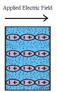
Figure 1
Glass and plastics are two example of di-electric material.
Want to see more full solutions like this?
Subscribe now to access step-by-step solutions to millions of textbook problems written by subject matter experts!
Students have asked these similar questions
Section 15-3 reversing motors using magnetic starters.Section 15-3Use data sheet B on page 383 to draw the wiring diagram. Note: use only the number of contacts required.
First 1. Wire the motor to operate in forward and reverse at 115 VAC.
Please solution
Use data sheet B on page 383 to draw the wiring diagram. Note: use only the number of contacts required.
First 1. Wire the motor to operate in forward and reverse at 115 VAC.
Chapter 3 Solutions
Electrical Engineering: Principles & Applications (7th Edition)
Ch. 3 - What is a dielectric material? Give two examples.Ch. 3 - Briefly discuss how current can flow “through” a...Ch. 3 - What current flows through an ideal capacitor if...Ch. 3 - Describe the internal construction of capacitors.Ch. 3 - A voltage of 50 V appears across a 10F capacitor....Ch. 3 - A 2000F capacitor, initially charged to 100V, is...Ch. 3 - A 5F Capacitor ischarged to 1000 V. Determine the...Ch. 3 - The voltage across a 10F capacitor is given by v...Ch. 3 - The voltage across a 1F capacitor is given by...Ch. 3 - Prior to t = 0, a 100F capacitance is uncharged...
Ch. 3 - The current through a 0.5F capacitor is shown in...Ch. 3 - Determine the capacitor voltage, power, and stored...Ch. 3 - A current given by i(t)=Imcos(t) flows through a...Ch. 3 - The current through a 3F capacitor is shown in...Ch. 3 - A constant (dc) current i(t)=3 mA flows into a 50F...Ch. 3 - The energy stored in a 2F capacitor is 200 J and...Ch. 3 - At t=t0 the voltage across a certain capacitance...Ch. 3 - An unusual capacitor has a capacitance that is a...Ch. 3 - For a resistor, what resistance corresponds to a...Ch. 3 - Suppose we have a very large capacitance (ideally,...Ch. 3 - We want to store sufficient energy in a 001-F...Ch. 3 - A 100F capacitor has a voltage given by v(t)=1010...Ch. 3 - How are capacitances combined in series and in...Ch. 3 - Find the equivalent capacitance for each of the...Ch. 3 - Find the equivalent capacitance between terminals...Ch. 3 - A network has a 5F capacitance in series with the...Ch. 3 - What are the minimum and maximum values of...Ch. 3 - Two initially uncharged capacitors C1=15F and...Ch. 3 - Suppose that we are designing a cardiac pacemaker...Ch. 3 - Suppose that we have two 100F capacitors One is...Ch. 3 - Determine the capacitance of a parallel-plate...Ch. 3 - A 100-pF capacitor is constructed of parallel...Ch. 3 - We have a parallel-plate capacitor with plates of...Ch. 3 - Suppose that we have a 1000-pF parallel-plate...Ch. 3 - Two 1F capacitors have an initial voltage of 100 V...Ch. 3 - Prob. 3.36PCh. 3 - Prob. 3.37PCh. 3 - A parallel-plate capacitor is used as a vibration...Ch. 3 - A 0.1F capacitor has a parasitic series resistance...Ch. 3 - Prob. 3.40PCh. 3 - Briefly discuss how inductors are constructed.Ch. 3 - The current flowing through an inductor is...Ch. 3 - If the current through an ideal inductor is...Ch. 3 - Briefly discuss the fluid-flow analogy for an...Ch. 3 - The current flowing through a 2-H inductance is...Ch. 3 - The current flowing through a 100-mH inductance is...Ch. 3 - The current flowing through a 2-H inductance is...Ch. 3 - The voltage across a 2-H inductance is shown in...Ch. 3 - The voltage across a 10 H inductance is given by...Ch. 3 - A 2-H inductance has i(0) = 0 and v(t)=texp(t) for...Ch. 3 - A constant voltage of 10V is applied to a 50H...Ch. 3 - At t = 0, the current flowing in a 05-H inductance...Ch. 3 - The current through a 100-mH inductance is given...Ch. 3 - Prior to t= 0, the current in a 2-H inductance is...Ch. 3 - At t= 0, a constant 5-V voltage source is applied...Ch. 3 - Prob. 3.56PCh. 3 - Al t= 5 s, the energy stored in a 2-H inductor is...Ch. 3 - What value of inductance (having zero initial...Ch. 3 - To what circuit element does a very large...Ch. 3 - The voltage across an inductance L is given by...Ch. 3 - Discuss how inductances are combined in series and...Ch. 3 - Determine the equivalent inductance for each of...Ch. 3 - Find the equivalent inductance for each of the...Ch. 3 - What is the maximum inductance that can be...Ch. 3 - Suppose we want to combine (in series or in...Ch. 3 - Prob. 3.66PCh. 3 - Two inductances L1=1H and L2=2H are connected in...Ch. 3 - A 10-mH inductor has a parasitic series resistance...Ch. 3 - Draw the equivalent circuit for a real inductor,...Ch. 3 - Suppose that the equivalent circuit shown in...Ch. 3 - Consider the circuit shown in Figure P3.71 in...Ch. 3 - The circuit shown in Figure P3.72 has...Ch. 3 - Describe briefly the physical basis for mutual...Ch. 3 - The mutually coupled inductances in Figure P3.74...Ch. 3 - Repeat Problem P3.74 with the dot placed at the...Ch. 3 - a. Derive an expression for the equivalent...Ch. 3 - Consider the parallel inductors shown in Figure...Ch. 3 - Consider the mutually coupled inductors shown in...Ch. 3 - Mutually coupled inductances have...Ch. 3 - The current through a 200-mH inductance is given...Ch. 3 - A 1-H inductance has iL(0)=0 and vL(t)=texp(t) for...Ch. 3 - The current flowing through a 10F capacitor having...Ch. 3 - Determine the equivalent capacitance Ceq for...Ch. 3 - A certain parallel-plate capacitor has plate...Ch. 3 - A 2-mH inductance has iab=0.3sin(2000t)A . Find an...Ch. 3 - Determine the equivalent inductance Leq between...Ch. 3 - Given that vc(t)=10sin(1000t)V , find vs(t)in the...Ch. 3 - Prob. 3.7PTCh. 3 - The current flowing through a 20F capacitor having...
Knowledge Booster


Learn more about
Need a deep-dive on the concept behind this application? Look no further. Learn more about this topic, electrical-engineering and related others by exploring similar questions and additional content below.Similar questions
- B:A 20 MVA transformer which may be called upon to operate at 30% overload, feeds 11 KV busbars through a circuit breaker: other circuit breakers supply outgoing feeders. The transformer circuit breaker is equipped with 1000/5 A CTS and the feeder circuit breakers with 400/5 A CTS and all sets of CTs feed induction type over current relays. The relays on the feeder circuits breakers have a 125% plug setting, and 0.3 time setting. If 3 ph fault current of 5000 A flows from the transformer to one of the feeders, find the operating time of the feeder relay, the minimum plug setting of the transformer relay and its time setting assuming a discrimination time margin of 0.5 sec. Relays having the following characteristics for TMS=1 PSM T in sec. 2 3.6 5 10 15 20 10 6 3.9 2.8 2.2 2.1arrow_forward10.34 Determine the power readings of the two wattmetersshown in the circuit of Fig. P10.34 given that ZY = (15− j5) Warrow_forward10.29 A 208-V (rms) balanced three-phase source supports twoloads connected in parallel. Each load is itself a balanced threephaseload. Determine the line current, given that load 1 is 12 kVAat pf 1 = 0.7 leading and load 2 is 18 kVA at pf 2 = 0.9 lagging.arrow_forward
- 10.31 A 240-V (rms), 60-Hz Y-source is connected to a balancedthree-phase Y-load by four wires, one of which is the neutral wire.If the load is 400 kVA at pf old = 0.6 lagging, what size capacitorsshould be added to change the power factor to pf new = 0.95lagging?arrow_forwardCable A Cable A is a coaxial cable of constant cross section. The metal regions are shaded in grey and are made of copper. The solid central wire has radius a = 5mm, the outer tube inner radius b = 20mm and thickness t = 5mm. The dielectric spacer is Teflon, of relative permittivity &r = 2.1 and breakdown strength 350kV/cm. A potential difference of 1kV is applied across the conductors, with centre conductor positive and outer conductor earthed. Before undertaking any COMSOL simulations we'll first perform some theoretical analysis of Cable A based on the EN2076 lectures, to make sense of the simulations. Calculate the radial electric field of cable A at radial positions r b. Also calculate the maximum operating voltage of cable A, assuming a safety margin of ×2, and indicate where on the cable's cross section dielectric breakdown is most likely to occur.arrow_forward: For the gravity concrete dam shown in the figure, the following data are available: The factor of safety against sliding (F.S sliding)=1.2 Unit weight of concrete (Yconc)=24 KN/m³ - Neglect( Wave pressure, silt pressure, ice force and earth quake force) μ=0.65, (Ywater) = 9.81 KN/m³ Find factor of safety against overturning (F.S overturning) 6m3 80m Smarrow_forward
- I need help checking if its correct -E1 + VR1 + VR4 – E2 + VR3 = 0 -------> Loop 1 (a) R1(I1) + R4(I1 – I2) + R3(I1) = E1 + E2 ------> Loop 1 (b) R1(I1) + R4(I1) - R4(I2) + R3(I1) = E1 + E2 ------> Loop 1 (c) (R1 + R3 + R4) (I1) - R4(I2) = E1 + E2 ------> Loop 1 (d) Now that we have loop 1 equation will procced on finding the equation of I2 current loop. However, a reminder that because we are going in a clockwise direction, it goes against the direction of the current. As such we will get an equation for the matrix that will be: E2 – VR4 – VR2 + E3 = 0 ------> Loop 2 (a) -R4(I2 – I1) -R2(I2) = -E2 – E3 ------> Loop 2 (b) -R4(I2) + R4(I1) - R2(I2) = -E2 – E3 -----> Loop 2 (c) R4(I1) – (R4 + R2)(I2) = -E2 – E3 -----> Loop 2 (d) These two equations will be implemented to the matrix formula I = inv(A) * b R11 R12 (R1 + R3 + R4) -R4 -R4 R4 + R2arrow_forward10.2 For each of the following groups of sources, determineif the three sources constitute a balanced source, and if it is,determine if it has a positive or negative phase sequence.(a) va(t) = 169.7cos(377t +15◦) Vvb(t) = 169.7cos(377t −105◦) Vvc(t) = 169.7sin(377t −135◦) V(b) va(t) = 311cos(wt −12◦) Vvb(t) = 311cos(wt +108◦) Vvc(t) = 311cos(wt +228◦) V(c) V1 = 140 −140◦ VV2 = 114 −20◦ VV3 = 124 100◦ Varrow_forwardApply single-phase equivalency to determine the linecurrents in the Y-D network shown in Fig. P10.13. The loadimpedances are Zab = Zbc = Zca = (25+ j5) Warrow_forward
- 10.8 In the network of Fig. P10.8, Za = Zb = Zc = (25+ j5) W.Determine the line currents.arrow_forwardUsing D flip-flops, design a synchronous counter. The counter counts in the sequence 1,3,5,7, 1,7,5,3,1,3,5,7,.... when its enable input x is equal to 1; otherwise, the counter count 0. Present state Next state x=0 Next state x=1 Output SO 52 S1 1 S1 54 53 3 52 53 S2 56 51 0 $5 5 54 S4 53 0 55 58 57 7 56 56 55 0 57 S10 59 1 58 58 S7 0 59 S12 S11 7 $10 $10 59 0 $11 $14 $13 5 $12 S12 $11 0 513 $15 SO 3 S14 $14 S13 0 $15 515 SO 0 Explain how to get the table step by step with drawing the state diagram and finding the Karnaugh map.arrow_forwardFor the oscillator resonance circuit shown in Fig. (5), derive the oscillation frequency Feedback and open-loop gains. L₁ 5 mH (a) ell +10 V R₁ ww R3 S C2 HH 1 με 1000 pF 100 pF R₂ 1 με RA H (b) +9 V R4 CA 470 pF C₁ R3 HH 1 με R₁ ww L₁ 000 1.5 mH R₂ ww Hi 1 μF L2 m 10 mHarrow_forward
arrow_back_ios
SEE MORE QUESTIONS
arrow_forward_ios
Recommended textbooks for you
 Electricity for Refrigeration, Heating, and Air C...Mechanical EngineeringISBN:9781337399128Author:Russell E. SmithPublisher:Cengage Learning
Electricity for Refrigeration, Heating, and Air C...
Mechanical Engineering
ISBN:9781337399128
Author:Russell E. Smith
Publisher:Cengage Learning
Conductivity and Semiconductors; Author: Professor Dave Explains;https://www.youtube.com/watch?v=5zz6LlDVRl0;License: Standard Youtube License