
Basic Engineering Circuit Analysis
11th Edition
ISBN: 9781118539293
Author: J. David Irwin, R. Mark Nelms
Publisher: WILEY
expand_more
expand_more
format_list_bulleted
Videos
Textbook Question
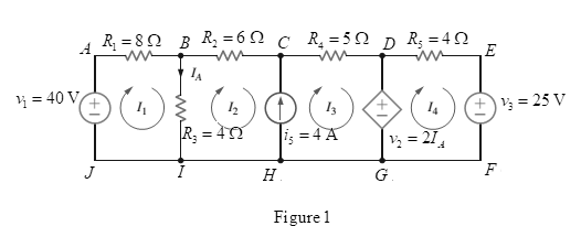
Chapter 3, Problem 116P
Solve for the assigned mesh currents in the network in Fig. P3.116.
Expert Solution & Answer
Want to see the full answer?
Check out a sample textbook solution
Students have asked these similar questions
8.24 In the circuit of Fig. P8.24, is(t) = 0.2sin105t A,R = 20 W, L = 0.1 mH, and C = 2 μF. Show that the sum ofthe complex powers for the three passive elements is equal to thecomplex power of the source.
3. VEB (on) 0.7 V, VEC (sat) = 0.2 V, and ẞ = 150. RB = 50 kQ, Rc = 2 kQ, and Vcc =
5 V.
a) Find the range of V₁ for the cut-off. Forward active, and saturation regions. (20
points)
b) Draw the voltage transfer characteristic (VTC) graph. (10 points)
Vcc
VEB
V₁
RB
www
。 Vo
Rc
Figure 3
2-1) Lathi & Ding prob. 2.5-2 For the signals y(t) and x(t) shown below, find the component of the form
y(t) contained in x(t). In other words, find the optimum value of c in the approximation x(t) = cy(t) so that
the error signal energy is minimum. Also compute the error signal energy.
y(t)
x(t)
0
1
0
1
Chapter 3 Solutions
Basic Engineering Circuit Analysis
Ch. 3 - Use nodal analysis to find V1 in the circuit in...Ch. 3 - Find both Io and Vo in the network in Fig. P3.2...Ch. 3 - Find I1 in the network in Fig. P3.3.Ch. 3 - Find I1 in the circuit in Fig. P3.4.Ch. 3 - Use nodal analysis to find V1 in the circuit in...Ch. 3 - Find V1 and V2 in the circuit in Fig. P3.6 using...Ch. 3 - Use nodal analysis to find both V1 and Vo in the...Ch. 3 - Write the node equations for the circuit in Fig....Ch. 3 - Find Vo in the network in Fig. P3.9.Ch. 3 - Find Io in the circuit in Fig. P3.10 using nodal...
Ch. 3 - Use nodal analysis to find Io in the network in...Ch. 3 - Use nodal analysis to find Vo in the circuit in...Ch. 3 - Find Vo in the network in Fig. P3.13 using nodal...Ch. 3 - Use nodal analysis to find Vo in the circuit in...Ch. 3 - Find Io in the network in Fig. P3.15 using nodal...Ch. 3 - Use nodal analysis to find Vo in the circuit in...Ch. 3 - Use nodal analysis to find Vo in the network in...Ch. 3 - Use nodal analysis to find Vo in the circuit in...Ch. 3 - Find Vo in the circuit in Fig. P3.19 using...Ch. 3 - Find Vo in the network in Fig. P3.20 using nodal...Ch. 3 - Find Vo in the network in Fig. P3.21 using nodal...Ch. 3 - Find Io in the circuit in Fig. P3.22 using nodal...Ch. 3 - Use nodal analysis to determine the node voltages...Ch. 3 - Use nodal analysis to find Vo in the network in...Ch. 3 - Use nodal analysis to find Vo in the circuit in...Ch. 3 - Use nodal analysis to solve for the node voltages...Ch. 3 - Find Vo in the network in Fig. P3.27 using nodal...Ch. 3 - Find Io in the network in Fig. P3.28 using nodal...Ch. 3 - Use nodal analysis to find Io in the circuit in...Ch. 3 - Find Vo in the circuit in Fig. P3.30 using nodal...Ch. 3 - Find Io in the circuit in Fig. P3.31 using nodal...Ch. 3 - Use nodal analysis to find Io in the circuit in...Ch. 3 - Using analysis, find Vo in the network in Fig....Ch. 3 - Find Vo in the network in Fig. P3.34 using nodal...Ch. 3 - Find Vo in the circuit in Fig. P3.35 using nodal...Ch. 3 - Find Vo in the circuit in Fig. P3.36 using nodal...Ch. 3 - Use nodal analysis to find Vo in the circuit in...Ch. 3 - Find Vo in the circuit in Fig. P3.38 using nodal...Ch. 3 - Find Vo in the circuit in Fig. P3.39 using nodal...Ch. 3 - Use nodal analysis to find Vo in the circuit in...Ch. 3 - Find Vo in the network in Fig. P3.41.Ch. 3 - Find I0 in the network in Fig. P3.42 using nodal...Ch. 3 - Find Vo in the network in Fig. P3.43 using nodal...Ch. 3 - Find Io in the network in Fig. P3.44 using nodal...Ch. 3 - Find Vo in the network in Fig. P3.45 using nodal...Ch. 3 - Find Vo in the circuit in Fig. P3.46 using nodal...Ch. 3 - Find Io in the network in Fig. P3.47 using nodal...Ch. 3 - Use nodal analysis to find Vo in the circuit in...Ch. 3 - Find Vo in the network in Fig. P3.49 using nodal...Ch. 3 - Find Vo in the network in Fig. P3.50 using nodal...Ch. 3 - Find Vo in the circuit in Fig. P3.51.Ch. 3 - Use nodal analysis to find Vo in the circuit in...Ch. 3 - Determine Vo in the network in Fig. P3.53 using...Ch. 3 - Use nodal analysis to find Vo in the circuit in...Ch. 3 - Use nodal analysis to find Vo in the circuit in...Ch. 3 - Find Io in the circuit in Fig. B3.56 using nodal...Ch. 3 - Use nodal analysis to solve for IA in the network...Ch. 3 - Use nodal analysis to find Vo in the circuit in...Ch. 3 - Use nodal analysis to find V1,V2,V3, and V4 in the...Ch. 3 - Determine Vo in the network in Fig. P3.60 using...Ch. 3 - Use nodal analysis to find V1,V2,V3, and V4 in the...Ch. 3 - Use nodal analysis to determine the node voltages...Ch. 3 - Use nodal analysis to determine the node voltages...Ch. 3 - Use nodal analysis to determine the node voltages...Ch. 3 - Find Io in the network in Fig. P3.65 using mesh...Ch. 3 - Find Vo in the network in Fig. P3.66 using mesh...Ch. 3 - Find Vo in the network in Fig. P3.67 using mesh...Ch. 3 - Find Io in the circuit in Fig. P3.68 using mesh...Ch. 3 - Use mesh analysis to find Vo in the circuit in...Ch. 3 - Find Io in the circuit in Fig. P3.70 using mesh...Ch. 3 - Use mesh analysis to find Vo in the network in...Ch. 3 - Find Io in the circuit in Fig. P3.72.Ch. 3 - Find Vo in the circuit in Fig. P3.73 using mesh...Ch. 3 - Find Vo in Fig. P3.74 using mesh analysis.Ch. 3 - Use loop analysis to find Vo in the network in...Ch. 3 - Find Io in Fig. P3.76 using mesh analysis.Ch. 3 - Find Vo in the network in Fig. P3.77 using loop...Ch. 3 - Find Io in the circuit in Fig. P3.78 using loop...Ch. 3 - Find Vo in the circuit in Fig. P3.79 using mesh...Ch. 3 - Use mesh analysis to find Vo in the circuit in...Ch. 3 - Use mesh analysis to find Io in the network in...Ch. 3 - Use loop analysis to find Vo in the circuit in...Ch. 3 - Use loop analysis to calculate the power supplied...Ch. 3 - Use loop analysis to find Io and I1 in the network...Ch. 3 - Find Vo in the network in Fig. P3.85 using loop...Ch. 3 - Find Vo in the circuit in Fig. P3.86 using...Ch. 3 - Find Io in network in Fig. P3.87 using loop...Ch. 3 - Find Io in the network in Fig. P3.88 using loop...Ch. 3 - Use loop analysis to find Vo in the circuit in...Ch. 3 - Using loop analysis, find Vo in the network in...Ch. 3 - Find Io in the circuit in Fig. P3.91 using mesh...Ch. 3 - Use analysis to find Io in the network in Fig....Ch. 3 - Using loop analysis, find Io in the circuit in...Ch. 3 - Find the mesh currents in the network in Fig....Ch. 3 - Using loop analysis, find Vo in the circuit in...Ch. 3 - Using loop analysis, find Vo in the network in...Ch. 3 - Find Io in the circuit in Fig. P3.97 using loop...Ch. 3 - Find Io in the network in Fig. P3.98 using loop...Ch. 3 - Find Vo in the circuit in Fig. P3.99 using loop...Ch. 3 - Use nodal analysis to find Vo in Fig. P3.100.Ch. 3 - Find Vo in the circuit in Fig. P3.101 using nodal...Ch. 3 - Use loop analysis to find Vo in the network in...Ch. 3 - Use nodal analysis to find Vo in the network in...Ch. 3 - Find Vo in the network in Fig. P3.104 using nodal...Ch. 3 - Find the power supplied by the 2-A current source...Ch. 3 - Find Io in the network in Fig. P3.106 using nodal...Ch. 3 - Find Vo in the circuit in Fig. P3.107 using loop...Ch. 3 - Use mesh analysis to find Vo in the circuit in...Ch. 3 - Using mesh analysis, find Vo in the circuit in...Ch. 3 - Find Vo in the circuit in Fig. P3.110 using nodal...Ch. 3 - Find Vx in the circuit in Fig. P3.111.Ch. 3 - Find Io in the circuit in Fig. P3.112.Ch. 3 - Write mesh equations for the circuit in Fig....Ch. 3 - Find Ix in the circuit in Fig. P3.114 using loop...Ch. 3 - Solve for the mesh currents defined in the circuit...Ch. 3 - Solve for the assigned mesh currents in the...Ch. 3 - Using the assigned mesh currents shown in Fig....Ch. 3 - Find Vo in the network in Fig. B3.118.Ch. 3 - Using loop analysis, find Vo in the circuit in...Ch. 3 - Using loop analysis, find Vo in the circuit in...Ch. 3 - Using loop analysis, find Vo in the network in...Ch. 3 - Using loop analysis, find Vo in the circuit in...Ch. 3 - Using loop analysis, find Io in the network in...Ch. 3 - Use analysis to find Io in the circuit in Fig....Ch. 3 - Find Vo in the circuit in Fig. P3.125 using loop...Ch. 3 - Using loop analysis, find Io in the circuit in...Ch. 3 - Use mesh analysis to determine the power delivered...Ch. 3 - Use mesh analysis to find the power delivered by...Ch. 3 - Use nodal analysis to find Vo in the circuit in...Ch. 3 - Find Io in the network in Fig. P3.130 using nodal...Ch. 3 - Find Vo in the circuit in Fig. 3PFE-l. a. 3.33 Vc....Ch. 3 - Determine the power dissipated in the 6-ohm...Ch. 3 - Find the current Ix in the 4-ohm resistor in the...Ch. 3 - Determine the voltage Vo in the circuit in Fig....Ch. 3 - What is the voltage V1 in the circuit in Fig....
Knowledge Booster


Learn more about
Need a deep-dive on the concept behind this application? Look no further. Learn more about this topic, electrical-engineering and related others by exploring similar questions and additional content below.Similar questions
- 1. Is1 = 2ls2 = 4 × 10-16 A, B₁ = ẞ2 = 100, and R₁ = 5 kQ. Find the VB such that lx = 1 mA. (30 points) R1 ww Q2 + VB Figure 1arrow_forward2-2) Lathi & Ding prob. 2.6-1 2.6-1 Find the correlation coefficient p between of signal x(t) and each of the four pulses g1(1), 82(1), 83(1), and g4(f) shown in Fig. P2.6-1. To provide maximum margin against the noise along the transmission path, which pair of pulses would you select for a binary communication? Figure P.2.6-1 x(f) (a) 8(1) (b) 82(1) (c) 1 1 sin 2πt sin 4πt -sin 2 0 0.707 83(1) 0 1 (d) 0 M P 0.707 84(1) (e) 0 0.5 -0.707arrow_forward2. Determine the operation point and the small-signal model of Q₁ for each of the circuits shown in Fig. 2. Assume Is = 8 × 10-16 A, B = 100 and VA = ∞. a) 20 points b) 20 points 0.8 V RC 50 Ω + Vcc = 2.5 V 4A" Figure 2-a Rc1kQ + Vcc = 2.5 V Figure 2-barrow_forward
- Please explain in detail how to solve this question. Include steps with calculations and theory. thank youarrow_forwardFinding crystallographic direction Z pt. 2 head pt. 1: ៩ Example 2: pt. 1 x₁ = a, y₁ = b/2, z₁ = 0 pt. 2 x2=-a, y₂ = b, Z₂ = c -a-a b-b/2 c-0 a b c tail => -2, 1/2, 1 Multiplying by 2 to eliminate the fraction -4,1,2 => [412] where the overbar represents a negative index families of directionsarrow_forwardCrystallographic planes Crystallographic planes are denoted by Miller indices. 5b Algorithm for Miller indices 1. Read off intercepts of plane with axes in terms of a, b, c 2. Take reciprocals of intercepts 3. Reduce to smallest integer values 4. Enclose in parentheses, no commas. 353 1/3 1/5 1/3 535 (535) In the cubic system, a plane and a direction with the same indices are orthogonal. E.g. [100] direction is perpendicular to (100) plane. Correspondingly, [123] direction is perpendicular to (123) plane. [2,3,3] Plane intercepts axes at 3a, 2b, 2c 2 11 1 Reciprocal numbers are: 3'2'2 b. Indices of the plane (Miller): (2,3,3) 2 a Indices of the direction: [2,3,3] X (200) (100) (110) (111) (100) Indices of crystallographic plane can be found from cross product of indices of any two non-parallel directions in this plane.arrow_forward
- Crystallographic positions Crystallographic position is denoted by three numbers, which are coefficients of the position vector, e.g. ½½½ for the red atom. Here the 'new' atom is at a/2 + b/2 + c/2 Silicon crystal has so-called "diamond type lattice". Each Si atom has 4 nearest neighbors. Diamond lattice starts with a FCC lattice and then adds four additional INTERNAL atoms at locations r = a/4+b/4+c/4 away from each of the atoms. In other words, diamond lattice is formed by two FCC lattices sifted by the vector r.arrow_forwardfind the answers for this prelabarrow_forwardQ2: (30 Marks) Design a DC/DC converter that produce output waveforms that shown in figures below from a fixed DC source of 20 volts. Vo (Volt) 14.1 IL (Amp) 13.9 2.25 1.75 † (msec) Output voltage 0.18 0.2 t (msec) L 0.214 0.22 Output currentarrow_forward
arrow_back_ios
SEE MORE QUESTIONS
arrow_forward_ios
Recommended textbooks for you
 Introductory Circuit Analysis (13th Edition)Electrical EngineeringISBN:9780133923605Author:Robert L. BoylestadPublisher:PEARSON
 Delmar's Standard Textbook Of ElectricityElectrical EngineeringISBN:9781337900348Author:Stephen L. HermanPublisher:Cengage Learning
 Programmable Logic ControllersElectrical EngineeringISBN:9780073373843Author:Frank D. PetruzellaPublisher:McGraw-Hill Education
 Fundamentals of Electric CircuitsElectrical EngineeringISBN:9780078028229Author:Charles K Alexander, Matthew SadikuPublisher:McGraw-Hill Education
 Electric Circuits. (11th Edition)Electrical EngineeringISBN:9780134746968Author:James W. Nilsson, Susan RiedelPublisher:PEARSON
 Engineering ElectromagneticsElectrical EngineeringISBN:9780078028151Author:Hayt, William H. (william Hart), Jr, BUCK, John A.Publisher:Mcgraw-hill Education,
Introductory Circuit Analysis (13th Edition)
Electrical Engineering
ISBN:9780133923605
Author:Robert L. Boylestad
Publisher:PEARSON
Delmar's Standard Textbook Of Electricity
Electrical Engineering
ISBN:9781337900348
Author:Stephen L. Herman
Publisher:Cengage Learning
Programmable Logic Controllers
Electrical Engineering
ISBN:9780073373843
Author:Frank D. Petruzella
Publisher:McGraw-Hill Education
Fundamentals of Electric Circuits
Electrical Engineering
ISBN:9780078028229
Author:Charles K Alexander, Matthew Sadiku
Publisher:McGraw-Hill Education
Electric Circuits. (11th Edition)
Electrical Engineering
ISBN:9780134746968
Author:James W. Nilsson, Susan Riedel
Publisher:PEARSON
Engineering Electromagnetics
Electrical Engineering
ISBN:9780078028151
Author:Hayt, William H. (william Hart), Jr, BUCK, John A.
Publisher:Mcgraw-hill Education,
Mesh Current Problems in Circuit Analysis - Electrical Circuits Crash Course - Beginners Electronics; Author: Math and Science;https://www.youtube.com/watch?v=DYg8B-ElK0s;License: Standard Youtube License