
Basic Engineering Circuit Analysis
11th Edition
ISBN: 9781118539293
Author: J. David Irwin, R. Mark Nelms
Publisher: WILEY
expand_more
expand_more
format_list_bulleted
Videos
Textbook Question
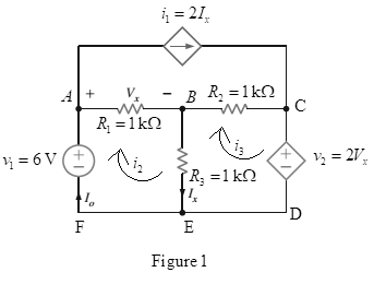
Chapter 3, Problem 124P
Use analysis to find
Expert Solution & Answer
Want to see the full answer?
Check out a sample textbook solution
Students have asked these similar questions
1. In the following closed-loop system, a PD controller of the form K(s + 5) is used. Design the gain K such
that the system achieves an overshoot of 16%. Calculate the settling time and peak time for the PD
controlled system.
Compensator
R(s) +
E(s)
Plant
1
C(s)
K(s+Zc)
(s+1)(s+2)(s+5)
Find Vo
3. Use MATLAB to generate the Nyquist plot for the following system. Then, apply the Nyquist stability
criterion to determine the range of K values that ensure the stability of the closed-loop system.
R(s)+
K
C(s)
(s+2)
1
(s + 4)(s+6)
Chapter 3 Solutions
Basic Engineering Circuit Analysis
Ch. 3 - Use nodal analysis to find V1 in the circuit in...Ch. 3 - Find both Io and Vo in the network in Fig. P3.2...Ch. 3 - Find I1 in the network in Fig. P3.3.Ch. 3 - Find I1 in the circuit in Fig. P3.4.Ch. 3 - Use nodal analysis to find V1 in the circuit in...Ch. 3 - Find V1 and V2 in the circuit in Fig. P3.6 using...Ch. 3 - Use nodal analysis to find both V1 and Vo in the...Ch. 3 - Write the node equations for the circuit in Fig....Ch. 3 - Find Vo in the network in Fig. P3.9.Ch. 3 - Find Io in the circuit in Fig. P3.10 using nodal...
Ch. 3 - Use nodal analysis to find Io in the network in...Ch. 3 - Use nodal analysis to find Vo in the circuit in...Ch. 3 - Find Vo in the network in Fig. P3.13 using nodal...Ch. 3 - Use nodal analysis to find Vo in the circuit in...Ch. 3 - Find Io in the network in Fig. P3.15 using nodal...Ch. 3 - Use nodal analysis to find Vo in the circuit in...Ch. 3 - Use nodal analysis to find Vo in the network in...Ch. 3 - Use nodal analysis to find Vo in the circuit in...Ch. 3 - Find Vo in the circuit in Fig. P3.19 using...Ch. 3 - Find Vo in the network in Fig. P3.20 using nodal...Ch. 3 - Find Vo in the network in Fig. P3.21 using nodal...Ch. 3 - Find Io in the circuit in Fig. P3.22 using nodal...Ch. 3 - Use nodal analysis to determine the node voltages...Ch. 3 - Use nodal analysis to find Vo in the network in...Ch. 3 - Use nodal analysis to find Vo in the circuit in...Ch. 3 - Use nodal analysis to solve for the node voltages...Ch. 3 - Find Vo in the network in Fig. P3.27 using nodal...Ch. 3 - Find Io in the network in Fig. P3.28 using nodal...Ch. 3 - Use nodal analysis to find Io in the circuit in...Ch. 3 - Find Vo in the circuit in Fig. P3.30 using nodal...Ch. 3 - Find Io in the circuit in Fig. P3.31 using nodal...Ch. 3 - Use nodal analysis to find Io in the circuit in...Ch. 3 - Using analysis, find Vo in the network in Fig....Ch. 3 - Find Vo in the network in Fig. P3.34 using nodal...Ch. 3 - Find Vo in the circuit in Fig. P3.35 using nodal...Ch. 3 - Find Vo in the circuit in Fig. P3.36 using nodal...Ch. 3 - Use nodal analysis to find Vo in the circuit in...Ch. 3 - Find Vo in the circuit in Fig. P3.38 using nodal...Ch. 3 - Find Vo in the circuit in Fig. P3.39 using nodal...Ch. 3 - Use nodal analysis to find Vo in the circuit in...Ch. 3 - Find Vo in the network in Fig. P3.41.Ch. 3 - Find I0 in the network in Fig. P3.42 using nodal...Ch. 3 - Find Vo in the network in Fig. P3.43 using nodal...Ch. 3 - Find Io in the network in Fig. P3.44 using nodal...Ch. 3 - Find Vo in the network in Fig. P3.45 using nodal...Ch. 3 - Find Vo in the circuit in Fig. P3.46 using nodal...Ch. 3 - Find Io in the network in Fig. P3.47 using nodal...Ch. 3 - Use nodal analysis to find Vo in the circuit in...Ch. 3 - Find Vo in the network in Fig. P3.49 using nodal...Ch. 3 - Find Vo in the network in Fig. P3.50 using nodal...Ch. 3 - Find Vo in the circuit in Fig. P3.51.Ch. 3 - Use nodal analysis to find Vo in the circuit in...Ch. 3 - Determine Vo in the network in Fig. P3.53 using...Ch. 3 - Use nodal analysis to find Vo in the circuit in...Ch. 3 - Use nodal analysis to find Vo in the circuit in...Ch. 3 - Find Io in the circuit in Fig. B3.56 using nodal...Ch. 3 - Use nodal analysis to solve for IA in the network...Ch. 3 - Use nodal analysis to find Vo in the circuit in...Ch. 3 - Use nodal analysis to find V1,V2,V3, and V4 in the...Ch. 3 - Determine Vo in the network in Fig. P3.60 using...Ch. 3 - Use nodal analysis to find V1,V2,V3, and V4 in the...Ch. 3 - Use nodal analysis to determine the node voltages...Ch. 3 - Use nodal analysis to determine the node voltages...Ch. 3 - Use nodal analysis to determine the node voltages...Ch. 3 - Find Io in the network in Fig. P3.65 using mesh...Ch. 3 - Find Vo in the network in Fig. P3.66 using mesh...Ch. 3 - Find Vo in the network in Fig. P3.67 using mesh...Ch. 3 - Find Io in the circuit in Fig. P3.68 using mesh...Ch. 3 - Use mesh analysis to find Vo in the circuit in...Ch. 3 - Find Io in the circuit in Fig. P3.70 using mesh...Ch. 3 - Use mesh analysis to find Vo in the network in...Ch. 3 - Find Io in the circuit in Fig. P3.72.Ch. 3 - Find Vo in the circuit in Fig. P3.73 using mesh...Ch. 3 - Find Vo in Fig. P3.74 using mesh analysis.Ch. 3 - Use loop analysis to find Vo in the network in...Ch. 3 - Find Io in Fig. P3.76 using mesh analysis.Ch. 3 - Find Vo in the network in Fig. P3.77 using loop...Ch. 3 - Find Io in the circuit in Fig. P3.78 using loop...Ch. 3 - Find Vo in the circuit in Fig. P3.79 using mesh...Ch. 3 - Use mesh analysis to find Vo in the circuit in...Ch. 3 - Use mesh analysis to find Io in the network in...Ch. 3 - Use loop analysis to find Vo in the circuit in...Ch. 3 - Use loop analysis to calculate the power supplied...Ch. 3 - Use loop analysis to find Io and I1 in the network...Ch. 3 - Find Vo in the network in Fig. P3.85 using loop...Ch. 3 - Find Vo in the circuit in Fig. P3.86 using...Ch. 3 - Find Io in network in Fig. P3.87 using loop...Ch. 3 - Find Io in the network in Fig. P3.88 using loop...Ch. 3 - Use loop analysis to find Vo in the circuit in...Ch. 3 - Using loop analysis, find Vo in the network in...Ch. 3 - Find Io in the circuit in Fig. P3.91 using mesh...Ch. 3 - Use analysis to find Io in the network in Fig....Ch. 3 - Using loop analysis, find Io in the circuit in...Ch. 3 - Find the mesh currents in the network in Fig....Ch. 3 - Using loop analysis, find Vo in the circuit in...Ch. 3 - Using loop analysis, find Vo in the network in...Ch. 3 - Find Io in the circuit in Fig. P3.97 using loop...Ch. 3 - Find Io in the network in Fig. P3.98 using loop...Ch. 3 - Find Vo in the circuit in Fig. P3.99 using loop...Ch. 3 - Use nodal analysis to find Vo in Fig. P3.100.Ch. 3 - Find Vo in the circuit in Fig. P3.101 using nodal...Ch. 3 - Use loop analysis to find Vo in the network in...Ch. 3 - Use nodal analysis to find Vo in the network in...Ch. 3 - Find Vo in the network in Fig. P3.104 using nodal...Ch. 3 - Find the power supplied by the 2-A current source...Ch. 3 - Find Io in the network in Fig. P3.106 using nodal...Ch. 3 - Find Vo in the circuit in Fig. P3.107 using loop...Ch. 3 - Use mesh analysis to find Vo in the circuit in...Ch. 3 - Using mesh analysis, find Vo in the circuit in...Ch. 3 - Find Vo in the circuit in Fig. P3.110 using nodal...Ch. 3 - Find Vx in the circuit in Fig. P3.111.Ch. 3 - Find Io in the circuit in Fig. P3.112.Ch. 3 - Write mesh equations for the circuit in Fig....Ch. 3 - Find Ix in the circuit in Fig. P3.114 using loop...Ch. 3 - Solve for the mesh currents defined in the circuit...Ch. 3 - Solve for the assigned mesh currents in the...Ch. 3 - Using the assigned mesh currents shown in Fig....Ch. 3 - Find Vo in the network in Fig. B3.118.Ch. 3 - Using loop analysis, find Vo in the circuit in...Ch. 3 - Using loop analysis, find Vo in the circuit in...Ch. 3 - Using loop analysis, find Vo in the network in...Ch. 3 - Using loop analysis, find Vo in the circuit in...Ch. 3 - Using loop analysis, find Io in the network in...Ch. 3 - Use analysis to find Io in the circuit in Fig....Ch. 3 - Find Vo in the circuit in Fig. P3.125 using loop...Ch. 3 - Using loop analysis, find Io in the circuit in...Ch. 3 - Use mesh analysis to determine the power delivered...Ch. 3 - Use mesh analysis to find the power delivered by...Ch. 3 - Use nodal analysis to find Vo in the circuit in...Ch. 3 - Find Io in the network in Fig. P3.130 using nodal...Ch. 3 - Find Vo in the circuit in Fig. 3PFE-l. a. 3.33 Vc....Ch. 3 - Determine the power dissipated in the 6-ohm...Ch. 3 - Find the current Ix in the 4-ohm resistor in the...Ch. 3 - Determine the voltage Vo in the circuit in Fig....Ch. 3 - What is the voltage V1 in the circuit in Fig....
Knowledge Booster


Learn more about
Need a deep-dive on the concept behind this application? Look no further. Learn more about this topic, electrical-engineering and related others by exploring similar questions and additional content below.Similar questions
- 4. Please find the stability margins from the following Bode diagrams. Bode Diagram Phase (deg) Magnitude (dB) 50 -100 -90 -135 -180 -270 10" 10° Frequency (rad/sec) 10'arrow_forward2. Please use asymptotes to draw the Bode diagrams of the following transfer function. Please label the axes to show the cut-off frequencies and key values on vertical axes and label each asymptote with its slope. G(s) s+10 s(s²+10s+100)arrow_forwardFind Voarrow_forward
- J. na ul-n-1) X (n) = na^ = na^ u(-(n+1)) (1-1+4)= 741-1 4[cn+1)] +1 * Z (^- 1-1 (n-1) a て why ✓ (n) Z , ༥(-༡) ur-n) Znxcm) -Zx X (n) (n-1) a auc-n) = X(n) ぞ 2-9³arrow_forwardTurn trip logic into boolean algebra gates logic?arrow_forwardFind the Z-transform including the region of convergence for the following function 12 (¹)" [u(n) – u(n − 5)] -arrow_forward
- Find the inverse Z-traform of X(z)= z 2 +z (z-0.125)³ (z-0.25)arrow_forwardA separately excited 6-kilowatt generator has a terminal voltage of 135V at no load. At full load, the terminal voltage is 120V with speed and field excitation unchanged. Armature resistance = = 0.25 ohm. A. What is the amount of voltage decrease caused by armature reaction and the voltage regulation?arrow_forwardJ. A sampling system can be set to adjust its sampling rate in 25 He steps. Considering the signal spectra pleted below, specify the minimum sampling rate setting for the signals: a)x(1) b)(1)+(1) 985)+20 0,09 0:00 0,0 106) 100) SORO -2501 250V (1500+501) 。 1500+50V 201 2500arrow_forward
arrow_back_ios
SEE MORE QUESTIONS
arrow_forward_ios
Recommended textbooks for you
 Introductory Circuit Analysis (13th Edition)Electrical EngineeringISBN:9780133923605Author:Robert L. BoylestadPublisher:PEARSON
 Delmar's Standard Textbook Of ElectricityElectrical EngineeringISBN:9781337900348Author:Stephen L. HermanPublisher:Cengage Learning
 Programmable Logic ControllersElectrical EngineeringISBN:9780073373843Author:Frank D. PetruzellaPublisher:McGraw-Hill Education
 Fundamentals of Electric CircuitsElectrical EngineeringISBN:9780078028229Author:Charles K Alexander, Matthew SadikuPublisher:McGraw-Hill Education
 Electric Circuits. (11th Edition)Electrical EngineeringISBN:9780134746968Author:James W. Nilsson, Susan RiedelPublisher:PEARSON
 Engineering ElectromagneticsElectrical EngineeringISBN:9780078028151Author:Hayt, William H. (william Hart), Jr, BUCK, John A.Publisher:Mcgraw-hill Education,
Introductory Circuit Analysis (13th Edition)
Electrical Engineering
ISBN:9780133923605
Author:Robert L. Boylestad
Publisher:PEARSON
Delmar's Standard Textbook Of Electricity
Electrical Engineering
ISBN:9781337900348
Author:Stephen L. Herman
Publisher:Cengage Learning
Programmable Logic Controllers
Electrical Engineering
ISBN:9780073373843
Author:Frank D. Petruzella
Publisher:McGraw-Hill Education
Fundamentals of Electric Circuits
Electrical Engineering
ISBN:9780078028229
Author:Charles K Alexander, Matthew Sadiku
Publisher:McGraw-Hill Education
Electric Circuits. (11th Edition)
Electrical Engineering
ISBN:9780134746968
Author:James W. Nilsson, Susan Riedel
Publisher:PEARSON
Engineering Electromagnetics
Electrical Engineering
ISBN:9780078028151
Author:Hayt, William H. (william Hart), Jr, BUCK, John A.
Publisher:Mcgraw-hill Education,
Mesh Current Problems in Circuit Analysis - Electrical Circuits Crash Course - Beginners Electronics; Author: Math and Science;https://www.youtube.com/watch?v=DYg8B-ElK0s;License: Standard Youtube License