
Basic Engineering Circuit Analysis
11th Edition
ISBN: 9781118539293
Author: J. David Irwin, R. Mark Nelms
Publisher: WILEY
expand_more
expand_more
format_list_bulleted
Videos
Textbook Question
Chapter 3, Problem 92P
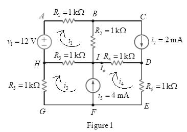
Use analysis to find
Expert Solution & Answer
Want to see the full answer?
Check out a sample textbook solution
Students have asked these similar questions
Find Vo
3. Use MATLAB to generate the Nyquist plot for the following system. Then, apply the Nyquist stability
criterion to determine the range of K values that ensure the stability of the closed-loop system.
R(s)+
K
C(s)
(s+2)
1
(s + 4)(s+6)
4. Please find the stability margins from the following Bode diagrams.
Bode Diagram
Phase (deg)
Magnitude (dB)
50
-100
-90
-135
-180
-270
10"
10°
Frequency (rad/sec)
10'
Chapter 3 Solutions
Basic Engineering Circuit Analysis
Ch. 3 - Use nodal analysis to find V1 in the circuit in...Ch. 3 - Find both Io and Vo in the network in Fig. P3.2...Ch. 3 - Find I1 in the network in Fig. P3.3.Ch. 3 - Find I1 in the circuit in Fig. P3.4.Ch. 3 - Use nodal analysis to find V1 in the circuit in...Ch. 3 - Find V1 and V2 in the circuit in Fig. P3.6 using...Ch. 3 - Use nodal analysis to find both V1 and Vo in the...Ch. 3 - Write the node equations for the circuit in Fig....Ch. 3 - Find Vo in the network in Fig. P3.9.Ch. 3 - Find Io in the circuit in Fig. P3.10 using nodal...
Ch. 3 - Use nodal analysis to find Io in the network in...Ch. 3 - Use nodal analysis to find Vo in the circuit in...Ch. 3 - Find Vo in the network in Fig. P3.13 using nodal...Ch. 3 - Use nodal analysis to find Vo in the circuit in...Ch. 3 - Find Io in the network in Fig. P3.15 using nodal...Ch. 3 - Use nodal analysis to find Vo in the circuit in...Ch. 3 - Use nodal analysis to find Vo in the network in...Ch. 3 - Use nodal analysis to find Vo in the circuit in...Ch. 3 - Find Vo in the circuit in Fig. P3.19 using...Ch. 3 - Find Vo in the network in Fig. P3.20 using nodal...Ch. 3 - Find Vo in the network in Fig. P3.21 using nodal...Ch. 3 - Find Io in the circuit in Fig. P3.22 using nodal...Ch. 3 - Use nodal analysis to determine the node voltages...Ch. 3 - Use nodal analysis to find Vo in the network in...Ch. 3 - Use nodal analysis to find Vo in the circuit in...Ch. 3 - Use nodal analysis to solve for the node voltages...Ch. 3 - Find Vo in the network in Fig. P3.27 using nodal...Ch. 3 - Find Io in the network in Fig. P3.28 using nodal...Ch. 3 - Use nodal analysis to find Io in the circuit in...Ch. 3 - Find Vo in the circuit in Fig. P3.30 using nodal...Ch. 3 - Find Io in the circuit in Fig. P3.31 using nodal...Ch. 3 - Use nodal analysis to find Io in the circuit in...Ch. 3 - Using analysis, find Vo in the network in Fig....Ch. 3 - Find Vo in the network in Fig. P3.34 using nodal...Ch. 3 - Find Vo in the circuit in Fig. P3.35 using nodal...Ch. 3 - Find Vo in the circuit in Fig. P3.36 using nodal...Ch. 3 - Use nodal analysis to find Vo in the circuit in...Ch. 3 - Find Vo in the circuit in Fig. P3.38 using nodal...Ch. 3 - Find Vo in the circuit in Fig. P3.39 using nodal...Ch. 3 - Use nodal analysis to find Vo in the circuit in...Ch. 3 - Find Vo in the network in Fig. P3.41.Ch. 3 - Find I0 in the network in Fig. P3.42 using nodal...Ch. 3 - Find Vo in the network in Fig. P3.43 using nodal...Ch. 3 - Find Io in the network in Fig. P3.44 using nodal...Ch. 3 - Find Vo in the network in Fig. P3.45 using nodal...Ch. 3 - Find Vo in the circuit in Fig. P3.46 using nodal...Ch. 3 - Find Io in the network in Fig. P3.47 using nodal...Ch. 3 - Use nodal analysis to find Vo in the circuit in...Ch. 3 - Find Vo in the network in Fig. P3.49 using nodal...Ch. 3 - Find Vo in the network in Fig. P3.50 using nodal...Ch. 3 - Find Vo in the circuit in Fig. P3.51.Ch. 3 - Use nodal analysis to find Vo in the circuit in...Ch. 3 - Determine Vo in the network in Fig. P3.53 using...Ch. 3 - Use nodal analysis to find Vo in the circuit in...Ch. 3 - Use nodal analysis to find Vo in the circuit in...Ch. 3 - Find Io in the circuit in Fig. B3.56 using nodal...Ch. 3 - Use nodal analysis to solve for IA in the network...Ch. 3 - Use nodal analysis to find Vo in the circuit in...Ch. 3 - Use nodal analysis to find V1,V2,V3, and V4 in the...Ch. 3 - Determine Vo in the network in Fig. P3.60 using...Ch. 3 - Use nodal analysis to find V1,V2,V3, and V4 in the...Ch. 3 - Use nodal analysis to determine the node voltages...Ch. 3 - Use nodal analysis to determine the node voltages...Ch. 3 - Use nodal analysis to determine the node voltages...Ch. 3 - Find Io in the network in Fig. P3.65 using mesh...Ch. 3 - Find Vo in the network in Fig. P3.66 using mesh...Ch. 3 - Find Vo in the network in Fig. P3.67 using mesh...Ch. 3 - Find Io in the circuit in Fig. P3.68 using mesh...Ch. 3 - Use mesh analysis to find Vo in the circuit in...Ch. 3 - Find Io in the circuit in Fig. P3.70 using mesh...Ch. 3 - Use mesh analysis to find Vo in the network in...Ch. 3 - Find Io in the circuit in Fig. P3.72.Ch. 3 - Find Vo in the circuit in Fig. P3.73 using mesh...Ch. 3 - Find Vo in Fig. P3.74 using mesh analysis.Ch. 3 - Use loop analysis to find Vo in the network in...Ch. 3 - Find Io in Fig. P3.76 using mesh analysis.Ch. 3 - Find Vo in the network in Fig. P3.77 using loop...Ch. 3 - Find Io in the circuit in Fig. P3.78 using loop...Ch. 3 - Find Vo in the circuit in Fig. P3.79 using mesh...Ch. 3 - Use mesh analysis to find Vo in the circuit in...Ch. 3 - Use mesh analysis to find Io in the network in...Ch. 3 - Use loop analysis to find Vo in the circuit in...Ch. 3 - Use loop analysis to calculate the power supplied...Ch. 3 - Use loop analysis to find Io and I1 in the network...Ch. 3 - Find Vo in the network in Fig. P3.85 using loop...Ch. 3 - Find Vo in the circuit in Fig. P3.86 using...Ch. 3 - Find Io in network in Fig. P3.87 using loop...Ch. 3 - Find Io in the network in Fig. P3.88 using loop...Ch. 3 - Use loop analysis to find Vo in the circuit in...Ch. 3 - Using loop analysis, find Vo in the network in...Ch. 3 - Find Io in the circuit in Fig. P3.91 using mesh...Ch. 3 - Use analysis to find Io in the network in Fig....Ch. 3 - Using loop analysis, find Io in the circuit in...Ch. 3 - Find the mesh currents in the network in Fig....Ch. 3 - Using loop analysis, find Vo in the circuit in...Ch. 3 - Using loop analysis, find Vo in the network in...Ch. 3 - Find Io in the circuit in Fig. P3.97 using loop...Ch. 3 - Find Io in the network in Fig. P3.98 using loop...Ch. 3 - Find Vo in the circuit in Fig. P3.99 using loop...Ch. 3 - Use nodal analysis to find Vo in Fig. P3.100.Ch. 3 - Find Vo in the circuit in Fig. P3.101 using nodal...Ch. 3 - Use loop analysis to find Vo in the network in...Ch. 3 - Use nodal analysis to find Vo in the network in...Ch. 3 - Find Vo in the network in Fig. P3.104 using nodal...Ch. 3 - Find the power supplied by the 2-A current source...Ch. 3 - Find Io in the network in Fig. P3.106 using nodal...Ch. 3 - Find Vo in the circuit in Fig. P3.107 using loop...Ch. 3 - Use mesh analysis to find Vo in the circuit in...Ch. 3 - Using mesh analysis, find Vo in the circuit in...Ch. 3 - Find Vo in the circuit in Fig. P3.110 using nodal...Ch. 3 - Find Vx in the circuit in Fig. P3.111.Ch. 3 - Find Io in the circuit in Fig. P3.112.Ch. 3 - Write mesh equations for the circuit in Fig....Ch. 3 - Find Ix in the circuit in Fig. P3.114 using loop...Ch. 3 - Solve for the mesh currents defined in the circuit...Ch. 3 - Solve for the assigned mesh currents in the...Ch. 3 - Using the assigned mesh currents shown in Fig....Ch. 3 - Find Vo in the network in Fig. B3.118.Ch. 3 - Using loop analysis, find Vo in the circuit in...Ch. 3 - Using loop analysis, find Vo in the circuit in...Ch. 3 - Using loop analysis, find Vo in the network in...Ch. 3 - Using loop analysis, find Vo in the circuit in...Ch. 3 - Using loop analysis, find Io in the network in...Ch. 3 - Use analysis to find Io in the circuit in Fig....Ch. 3 - Find Vo in the circuit in Fig. P3.125 using loop...Ch. 3 - Using loop analysis, find Io in the circuit in...Ch. 3 - Use mesh analysis to determine the power delivered...Ch. 3 - Use mesh analysis to find the power delivered by...Ch. 3 - Use nodal analysis to find Vo in the circuit in...Ch. 3 - Find Io in the network in Fig. P3.130 using nodal...Ch. 3 - Find Vo in the circuit in Fig. 3PFE-l. a. 3.33 Vc....Ch. 3 - Determine the power dissipated in the 6-ohm...Ch. 3 - Find the current Ix in the 4-ohm resistor in the...Ch. 3 - Determine the voltage Vo in the circuit in Fig....Ch. 3 - What is the voltage V1 in the circuit in Fig....
Knowledge Booster


Learn more about
Need a deep-dive on the concept behind this application? Look no further. Learn more about this topic, electrical-engineering and related others by exploring similar questions and additional content below.Similar questions
- Using Properties to find the Z-Transform including the region of convergence for Sol x(n): = n n cos(0.2(n-2))u(n - 1) Xch]=h+1-1 (1) h+h cos(0.27 (^_1_-1)) * shift → ht 44h-13 can you complete my solutionarrow_forwardFind Ixarrow_forwardJ. na ul-n-1) X (n) = na^ = na^ u(-(n+1)) (1-1+4)= 741-1 4[cn+1)] +1 * Z (^- 1-1 (n-1) a て why ✓ (n) Z , ༥(-༡) ur-n) Znxcm) -Zx X (n) (n-1) a auc-n) = X(n) ぞ 2-9³arrow_forward
- A separately excited 6-kilowatt generator has a terminal voltage of 135V at no load. At full load, the terminal voltage is 120V with speed and field excitation unchanged. Armature resistance = = 0.25 ohm. A. What is the amount of voltage decrease caused by armature reaction and the voltage regulation?arrow_forwardJ. A sampling system can be set to adjust its sampling rate in 25 He steps. Considering the signal spectra pleted below, specify the minimum sampling rate setting for the signals: a)x(1) b)(1)+(1) 985)+20 0,09 0:00 0,0 106) 100) SORO -2501 250V (1500+501) 。 1500+50V 201 2500arrow_forward1. For this problem, state your answers to 4 significant figures. (1)For the message signal shown below, sketch the phase-meduced form and 4-5/N rad V. Specify values of the miniman & maximum instantaneous frequencies in He (b) Find the approximate bandwidth of the phase-modulaud signal, assuming that the effective handwidth of the message is equal to its 4th harmonic frequency (N-2015 101 2x10' 159-arrow_forward
arrow_back_ios
SEE MORE QUESTIONS
arrow_forward_ios
Recommended textbooks for you
 Introductory Circuit Analysis (13th Edition)Electrical EngineeringISBN:9780133923605Author:Robert L. BoylestadPublisher:PEARSON
 Delmar's Standard Textbook Of ElectricityElectrical EngineeringISBN:9781337900348Author:Stephen L. HermanPublisher:Cengage Learning
 Programmable Logic ControllersElectrical EngineeringISBN:9780073373843Author:Frank D. PetruzellaPublisher:McGraw-Hill Education
 Fundamentals of Electric CircuitsElectrical EngineeringISBN:9780078028229Author:Charles K Alexander, Matthew SadikuPublisher:McGraw-Hill Education
 Electric Circuits. (11th Edition)Electrical EngineeringISBN:9780134746968Author:James W. Nilsson, Susan RiedelPublisher:PEARSON
 Engineering ElectromagneticsElectrical EngineeringISBN:9780078028151Author:Hayt, William H. (william Hart), Jr, BUCK, John A.Publisher:Mcgraw-hill Education,
Introductory Circuit Analysis (13th Edition)
Electrical Engineering
ISBN:9780133923605
Author:Robert L. Boylestad
Publisher:PEARSON
Delmar's Standard Textbook Of Electricity
Electrical Engineering
ISBN:9781337900348
Author:Stephen L. Herman
Publisher:Cengage Learning
Programmable Logic Controllers
Electrical Engineering
ISBN:9780073373843
Author:Frank D. Petruzella
Publisher:McGraw-Hill Education
Fundamentals of Electric Circuits
Electrical Engineering
ISBN:9780078028229
Author:Charles K Alexander, Matthew Sadiku
Publisher:McGraw-Hill Education
Electric Circuits. (11th Edition)
Electrical Engineering
ISBN:9780134746968
Author:James W. Nilsson, Susan Riedel
Publisher:PEARSON
Engineering Electromagnetics
Electrical Engineering
ISBN:9780078028151
Author:Hayt, William H. (william Hart), Jr, BUCK, John A.
Publisher:Mcgraw-hill Education,
Mesh Current Problems in Circuit Analysis - Electrical Circuits Crash Course - Beginners Electronics; Author: Math and Science;https://www.youtube.com/watch?v=DYg8B-ElK0s;License: Standard Youtube License