
Basic Engineering Circuit Analysis
11th Edition
ISBN: 9781118539293
Author: J. David Irwin, R. Mark Nelms
Publisher: WILEY
expand_more
expand_more
format_list_bulleted
Videos
Textbook Question
Chapter 3, Problem 115P
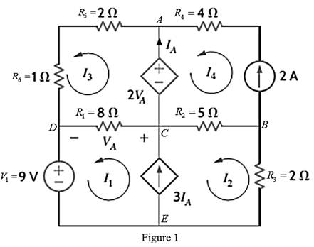
Solve for the mesh currents defined in the circuit in Fig. P3.115.
Expert Solution & Answer
Want to see the full answer?
Check out a sample textbook solution
Students have asked these similar questions
Pls show neat and whole solution
Pls show neat and whole solution
Need handwritten solution not using chatgpt Or AI
Chapter 3 Solutions
Basic Engineering Circuit Analysis
Ch. 3 - Use nodal analysis to find V1 in the circuit in...Ch. 3 - Find both Io and Vo in the network in Fig. P3.2...Ch. 3 - Find I1 in the network in Fig. P3.3.Ch. 3 - Find I1 in the circuit in Fig. P3.4.Ch. 3 - Use nodal analysis to find V1 in the circuit in...Ch. 3 - Find V1 and V2 in the circuit in Fig. P3.6 using...Ch. 3 - Use nodal analysis to find both V1 and Vo in the...Ch. 3 - Write the node equations for the circuit in Fig....Ch. 3 - Find Vo in the network in Fig. P3.9.Ch. 3 - Find Io in the circuit in Fig. P3.10 using nodal...
Ch. 3 - Use nodal analysis to find Io in the network in...Ch. 3 - Use nodal analysis to find Vo in the circuit in...Ch. 3 - Find Vo in the network in Fig. P3.13 using nodal...Ch. 3 - Use nodal analysis to find Vo in the circuit in...Ch. 3 - Find Io in the network in Fig. P3.15 using nodal...Ch. 3 - Use nodal analysis to find Vo in the circuit in...Ch. 3 - Use nodal analysis to find Vo in the network in...Ch. 3 - Use nodal analysis to find Vo in the circuit in...Ch. 3 - Find Vo in the circuit in Fig. P3.19 using...Ch. 3 - Find Vo in the network in Fig. P3.20 using nodal...Ch. 3 - Find Vo in the network in Fig. P3.21 using nodal...Ch. 3 - Find Io in the circuit in Fig. P3.22 using nodal...Ch. 3 - Use nodal analysis to determine the node voltages...Ch. 3 - Use nodal analysis to find Vo in the network in...Ch. 3 - Use nodal analysis to find Vo in the circuit in...Ch. 3 - Use nodal analysis to solve for the node voltages...Ch. 3 - Find Vo in the network in Fig. P3.27 using nodal...Ch. 3 - Find Io in the network in Fig. P3.28 using nodal...Ch. 3 - Use nodal analysis to find Io in the circuit in...Ch. 3 - Find Vo in the circuit in Fig. P3.30 using nodal...Ch. 3 - Find Io in the circuit in Fig. P3.31 using nodal...Ch. 3 - Use nodal analysis to find Io in the circuit in...Ch. 3 - Using analysis, find Vo in the network in Fig....Ch. 3 - Find Vo in the network in Fig. P3.34 using nodal...Ch. 3 - Find Vo in the circuit in Fig. P3.35 using nodal...Ch. 3 - Find Vo in the circuit in Fig. P3.36 using nodal...Ch. 3 - Use nodal analysis to find Vo in the circuit in...Ch. 3 - Find Vo in the circuit in Fig. P3.38 using nodal...Ch. 3 - Find Vo in the circuit in Fig. P3.39 using nodal...Ch. 3 - Use nodal analysis to find Vo in the circuit in...Ch. 3 - Find Vo in the network in Fig. P3.41.Ch. 3 - Find I0 in the network in Fig. P3.42 using nodal...Ch. 3 - Find Vo in the network in Fig. P3.43 using nodal...Ch. 3 - Find Io in the network in Fig. P3.44 using nodal...Ch. 3 - Find Vo in the network in Fig. P3.45 using nodal...Ch. 3 - Find Vo in the circuit in Fig. P3.46 using nodal...Ch. 3 - Find Io in the network in Fig. P3.47 using nodal...Ch. 3 - Use nodal analysis to find Vo in the circuit in...Ch. 3 - Find Vo in the network in Fig. P3.49 using nodal...Ch. 3 - Find Vo in the network in Fig. P3.50 using nodal...Ch. 3 - Find Vo in the circuit in Fig. P3.51.Ch. 3 - Use nodal analysis to find Vo in the circuit in...Ch. 3 - Determine Vo in the network in Fig. P3.53 using...Ch. 3 - Use nodal analysis to find Vo in the circuit in...Ch. 3 - Use nodal analysis to find Vo in the circuit in...Ch. 3 - Find Io in the circuit in Fig. B3.56 using nodal...Ch. 3 - Use nodal analysis to solve for IA in the network...Ch. 3 - Use nodal analysis to find Vo in the circuit in...Ch. 3 - Use nodal analysis to find V1,V2,V3, and V4 in the...Ch. 3 - Determine Vo in the network in Fig. P3.60 using...Ch. 3 - Use nodal analysis to find V1,V2,V3, and V4 in the...Ch. 3 - Use nodal analysis to determine the node voltages...Ch. 3 - Use nodal analysis to determine the node voltages...Ch. 3 - Use nodal analysis to determine the node voltages...Ch. 3 - Find Io in the network in Fig. P3.65 using mesh...Ch. 3 - Find Vo in the network in Fig. P3.66 using mesh...Ch. 3 - Find Vo in the network in Fig. P3.67 using mesh...Ch. 3 - Find Io in the circuit in Fig. P3.68 using mesh...Ch. 3 - Use mesh analysis to find Vo in the circuit in...Ch. 3 - Find Io in the circuit in Fig. P3.70 using mesh...Ch. 3 - Use mesh analysis to find Vo in the network in...Ch. 3 - Find Io in the circuit in Fig. P3.72.Ch. 3 - Find Vo in the circuit in Fig. P3.73 using mesh...Ch. 3 - Find Vo in Fig. P3.74 using mesh analysis.Ch. 3 - Use loop analysis to find Vo in the network in...Ch. 3 - Find Io in Fig. P3.76 using mesh analysis.Ch. 3 - Find Vo in the network in Fig. P3.77 using loop...Ch. 3 - Find Io in the circuit in Fig. P3.78 using loop...Ch. 3 - Find Vo in the circuit in Fig. P3.79 using mesh...Ch. 3 - Use mesh analysis to find Vo in the circuit in...Ch. 3 - Use mesh analysis to find Io in the network in...Ch. 3 - Use loop analysis to find Vo in the circuit in...Ch. 3 - Use loop analysis to calculate the power supplied...Ch. 3 - Use loop analysis to find Io and I1 in the network...Ch. 3 - Find Vo in the network in Fig. P3.85 using loop...Ch. 3 - Find Vo in the circuit in Fig. P3.86 using...Ch. 3 - Find Io in network in Fig. P3.87 using loop...Ch. 3 - Find Io in the network in Fig. P3.88 using loop...Ch. 3 - Use loop analysis to find Vo in the circuit in...Ch. 3 - Using loop analysis, find Vo in the network in...Ch. 3 - Find Io in the circuit in Fig. P3.91 using mesh...Ch. 3 - Use analysis to find Io in the network in Fig....Ch. 3 - Using loop analysis, find Io in the circuit in...Ch. 3 - Find the mesh currents in the network in Fig....Ch. 3 - Using loop analysis, find Vo in the circuit in...Ch. 3 - Using loop analysis, find Vo in the network in...Ch. 3 - Find Io in the circuit in Fig. P3.97 using loop...Ch. 3 - Find Io in the network in Fig. P3.98 using loop...Ch. 3 - Find Vo in the circuit in Fig. P3.99 using loop...Ch. 3 - Use nodal analysis to find Vo in Fig. P3.100.Ch. 3 - Find Vo in the circuit in Fig. P3.101 using nodal...Ch. 3 - Use loop analysis to find Vo in the network in...Ch. 3 - Use nodal analysis to find Vo in the network in...Ch. 3 - Find Vo in the network in Fig. P3.104 using nodal...Ch. 3 - Find the power supplied by the 2-A current source...Ch. 3 - Find Io in the network in Fig. P3.106 using nodal...Ch. 3 - Find Vo in the circuit in Fig. P3.107 using loop...Ch. 3 - Use mesh analysis to find Vo in the circuit in...Ch. 3 - Using mesh analysis, find Vo in the circuit in...Ch. 3 - Find Vo in the circuit in Fig. P3.110 using nodal...Ch. 3 - Find Vx in the circuit in Fig. P3.111.Ch. 3 - Find Io in the circuit in Fig. P3.112.Ch. 3 - Write mesh equations for the circuit in Fig....Ch. 3 - Find Ix in the circuit in Fig. P3.114 using loop...Ch. 3 - Solve for the mesh currents defined in the circuit...Ch. 3 - Solve for the assigned mesh currents in the...Ch. 3 - Using the assigned mesh currents shown in Fig....Ch. 3 - Find Vo in the network in Fig. B3.118.Ch. 3 - Using loop analysis, find Vo in the circuit in...Ch. 3 - Using loop analysis, find Vo in the circuit in...Ch. 3 - Using loop analysis, find Vo in the network in...Ch. 3 - Using loop analysis, find Vo in the circuit in...Ch. 3 - Using loop analysis, find Io in the network in...Ch. 3 - Use analysis to find Io in the circuit in Fig....Ch. 3 - Find Vo in the circuit in Fig. P3.125 using loop...Ch. 3 - Using loop analysis, find Io in the circuit in...Ch. 3 - Use mesh analysis to determine the power delivered...Ch. 3 - Use mesh analysis to find the power delivered by...Ch. 3 - Use nodal analysis to find Vo in the circuit in...Ch. 3 - Find Io in the network in Fig. P3.130 using nodal...Ch. 3 - Find Vo in the circuit in Fig. 3PFE-l. a. 3.33 Vc....Ch. 3 - Determine the power dissipated in the 6-ohm...Ch. 3 - Find the current Ix in the 4-ohm resistor in the...Ch. 3 - Determine the voltage Vo in the circuit in Fig....Ch. 3 - What is the voltage V1 in the circuit in Fig....
Additional Engineering Textbook Solutions
Find more solutions based on key concepts
Is a syntax error (such as misspelling a key word) found by the compiler or when the program is running?
Starting Out with Java: From Control Structures through Objects (7th Edition) (What's New in Computer Science)
Write a loop that counts the number of space characters that appear in the String object str.
Starting Out with Java: From Control Structures through Data Structures (4th Edition) (What's New in Computer Science)
What is an algorithm?
Starting Out With Visual Basic (8th Edition)
Prime Number List This exercise assumes that you have already written the is_prime function in Programming Exer...
Starting Out with Python (4th Edition)
Explain the term foreign key, and give an example.
Database Concepts (8th Edition)
Find the error in each of the following code segments, and explain how to correct it: 1 i = 1; 2 while (i = 10)...
Java How to Program, Early Objects (11th Edition) (Deitel: How to Program)
Knowledge Booster


Learn more about
Need a deep-dive on the concept behind this application? Look no further. Learn more about this topic, electrical-engineering and related others by exploring similar questions and additional content below.Similar questions
- 1) A circuit is given as shown. (a) Find and label the circuit nodes. (6) Determine I, II, I₂ and V, I mm 22 +1 m 50 4 12 12v 2 ти + V ≤1652 50 mv Ми 60arrow_forwardHANDWRITTEN SOLUTION NOT USING CHATGPT PLEASEarrow_forwardDesign a full-wave rectifier power supply using a 9.52:1 transformer. Assume that the outlet is120 V rms @ 60 Hz. Further assume that the diode turn-on voltage V D(on) is 0.7 V. Pick the valueof CL such that vo has a maximum ripple of 1 V p-p . Solve for the average value of vo = Vo (notethat this may be greater than 12 V) and iD(ave) = ID.arrow_forward
- Light-emitting diodes (LEDs) are diodes made with III-V compound semiconductor materials such as aluminum gallium arsenide (AlGaAs), aluminum indium gallium phosphide (AlInGaP) or indium gallium nitride (InGaN), instead of silicon. The LEDs emit light when the device is operated under forward bias. LEDs of different colors have different turn-on voltages VD(on). For example: VD(on) : Red: ~ 1.6 V Yellow: ~ 1.7 V Green: ~ 1.8 V Blue: ~ 2.8 V White: ~ 3.8 V (a) Model these five LEDs with a simplified piecewise linear model (b) A rule of thumb is that it takes about 1 mA of current to “light” an LED while ~ 10 mA is needed for it to appear bright. Use the piecewise linear model for the LEDs, for the over-voltage indicator circuit to the right, find the values of Vin which will cause D1 or D2 to light (i.e. when ID1 or ID2 exceeds 1 mA).arrow_forwardConsider a fixed and updated instrumentation amplifier (where two resistors are lumped into one resistor), analyze the circuit if a common voltage source (VICM) is connected to two inputs. A₁ R₂ + R₁ R₂, RA www www R₁ R₁ www A3 X R₁ R₂ www www R₁₂ + Vo RA A2 V2 O- + R₂ 12 R₁arrow_forwardShow that the input impedance of a lossy transmission line of length L connected to a load impedance of Z is given by Z₁Cosh(yL) + ZoSinh(yL) Zin = Zo ZoCosh(YL) + Z₁Sihh(YL) ex Where Cosh(x) = and Sinh(x) = are the hyperbolic cosine and sine, respectively. 2 2arrow_forward
- A sinusoidal source of V = 10 and Z = 50 - j40 is connected to a 60 lossless transmission line of length 100 m with ẞ = 0.25. What is the Thevenin's equivalent of this system seen looking into the load end of the transmission line?arrow_forward2. On a distortionless transmission line, the voltage wave is given by v(L,t) = 110e0.005L Cos(10³t + 2L) +55e-0.005L Cos(108t-2L) where L is the length of the transmission line as measured from the load. If Z = 30002, find a,ẞ, vp, and Zo.arrow_forwardA 50 transmission line is to be connected to a 72 load through a 1/4 quarter wave matching transformer. (a) What must be the characteristic impedance of the transmission line that is used to form the quarter wave transformer? (b) If the frequency of operation is 7 MHz and the phase velocity through the quarter wave section is 2c/3, what is the length of the quarter wave section? You may assume the transmission line forming the quarter wave section is lossless.arrow_forward
arrow_back_ios
SEE MORE QUESTIONS
arrow_forward_ios
Recommended textbooks for you
 Introductory Circuit Analysis (13th Edition)Electrical EngineeringISBN:9780133923605Author:Robert L. BoylestadPublisher:PEARSON
 Delmar's Standard Textbook Of ElectricityElectrical EngineeringISBN:9781337900348Author:Stephen L. HermanPublisher:Cengage Learning
 Programmable Logic ControllersElectrical EngineeringISBN:9780073373843Author:Frank D. PetruzellaPublisher:McGraw-Hill Education
 Fundamentals of Electric CircuitsElectrical EngineeringISBN:9780078028229Author:Charles K Alexander, Matthew SadikuPublisher:McGraw-Hill Education
 Electric Circuits. (11th Edition)Electrical EngineeringISBN:9780134746968Author:James W. Nilsson, Susan RiedelPublisher:PEARSON
 Engineering ElectromagneticsElectrical EngineeringISBN:9780078028151Author:Hayt, William H. (william Hart), Jr, BUCK, John A.Publisher:Mcgraw-hill Education,
Introductory Circuit Analysis (13th Edition)
Electrical Engineering
ISBN:9780133923605
Author:Robert L. Boylestad
Publisher:PEARSON
Delmar's Standard Textbook Of Electricity
Electrical Engineering
ISBN:9781337900348
Author:Stephen L. Herman
Publisher:Cengage Learning
Programmable Logic Controllers
Electrical Engineering
ISBN:9780073373843
Author:Frank D. Petruzella
Publisher:McGraw-Hill Education
Fundamentals of Electric Circuits
Electrical Engineering
ISBN:9780078028229
Author:Charles K Alexander, Matthew Sadiku
Publisher:McGraw-Hill Education
Electric Circuits. (11th Edition)
Electrical Engineering
ISBN:9780134746968
Author:James W. Nilsson, Susan Riedel
Publisher:PEARSON
Engineering Electromagnetics
Electrical Engineering
ISBN:9780078028151
Author:Hayt, William H. (william Hart), Jr, BUCK, John A.
Publisher:Mcgraw-hill Education,
Mesh Current Problems in Circuit Analysis - Electrical Circuits Crash Course - Beginners Electronics; Author: Math and Science;https://www.youtube.com/watch?v=DYg8B-ElK0s;License: Standard Youtube License