
University Physics (14th Edition)
14th Edition
ISBN: 9780133969290
Author: Hugh D. Young, Roger A. Freedman
Publisher: PEARSON
expand_more
expand_more
format_list_bulleted
Videos
Textbook Question
Chapter 26, Problem 26.18E
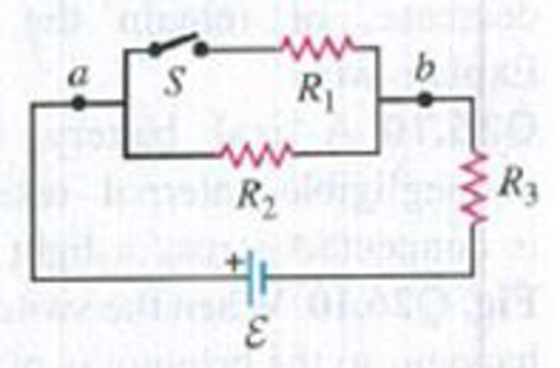
In the circuit shown in Fig. E26.18, ε = 36.0 V, R1, = 4.00 Ω, R2 = 6.00 Ω, and R3 = 3.00 Ω, (a) What is the potential difference Vab between points a and b when the switch S is open and when S is closed? (b) For each resistor, calculate the current through the resistor with S open and with S closed. For each resistor, does the current increase or decrease when S is closed?
Figure E26.18
Expert Solution & Answer
Want to see the full answer?
Check out a sample textbook solution
Students have asked these similar questions
You connect a battery, resistor, and a capacitor as in figure 1, where R= 15.0 ohms and C= 5.00x10^-6 F. The switch S is closed at t=0. When the current in the circuit has magnitude 3.00 A, the charge on the capacitor is 40.0x10^-6 C. (A) what is the emf of the battery? (B) at what time t after the switch is closed is the charge on the capacitor equal to 40.0x10^-6? (C) when the current has magnitude 3.00 A, at what rate is the energy being stored in the capacitor? (D) when the current has magnitude 3.00 A, at what rate is energy being supplied by the battery?
The figure shows an RC circuit. The switch S is initially open as depicted. We assume that
initially all capacitors are uncharged. At time t=0 the switch is closed. Find the current
through the red 5000 resistor
(a)
(b)
Just after the switch is closed.
When the switch has been closed for a long time.
12V-
S
m
500Ω
www
:5μF
2ΚΩ
500Ω
HE
2μF
M
2ΚΩ
www
1kΩ
2ΚΩ
3
Chapter 26 Solutions
University Physics (14th Edition)
Ch. 26 - In which 120-V light bulb does the filament have...Ch. 26 - Two 120-V light bulbs, one 25-W and one 200-W,...Ch. 26 - You connect a number of identical light bulbs to a...Ch. 26 - In the circuit shown in Fig. Q26.4, three...Ch. 26 - If two resistors R1 and R2 (R2 R1) are connected...Ch. 26 - If two resistors R1 and R2 (R2 R1) are connected...Ch. 26 - A battery with no internal resistance is connected...Ch. 26 - A resistor consists of three identical metal...Ch. 26 - A light bulb is connected in the circuit shown in...Ch. 26 - A real battery, having nonnegligible internal...
Ch. 26 - If the battery in Discussion Question Q26.10 is...Ch. 26 - Consider the circuit shown in Fig. Q26.12. What...Ch. 26 - Is it possible to connect resistors together in a...Ch. 26 - The battery in the circuit shown in Fig. Q26.14...Ch. 26 - In a two-cell flashlight, the batteries are...Ch. 26 - Identical light bulbs A, B, and C are connected as...Ch. 26 - The emf of a flashlight battery is roughly...Ch. 26 - Will the capacitors in the circuits shown in Fig....Ch. 26 - Verify that the time constant RC has units of...Ch. 26 - For very large resistances it is easy to construct...Ch. 26 - When a capacitor, battery, and resistor are...Ch. 26 - A uniform wire of resistance R is cut into three...Ch. 26 - A machine part has a resistor X protruding from an...Ch. 26 - A resistor with R1 = 25.0 is connected to a...Ch. 26 - A 42- resistor and a 20- resistor are connected in...Ch. 26 - A triangular array of resistors is shown in Fig....Ch. 26 - For the circuit shown in Fig. E26.6 both meters...Ch. 26 - For the circuit shown in Fig. E26.7 find the...Ch. 26 - Three resistors having resistances of 1.60 , 2.40...Ch. 26 - Now the three resistors of Exercise 26.8 are...Ch. 26 - Power Rating of a Resistor. The power rating of a...Ch. 26 - In Fig. E26.11, R1, = 3.00 , R2 = 6.00 , and R3=...Ch. 26 - In Fig. E26.11 the battery has emf 35.0 V and...Ch. 26 - Compute the equivalent resistance of the network...Ch. 26 - Compute the equivalent resistance of the network...Ch. 26 - In the circuit of Fig. E26.15, each resistor...Ch. 26 - Consider the circuit shown in Fig. E26.16. The...Ch. 26 - In the circuit shown in Fig. E26.17, the voltage...Ch. 26 - In the circuit shown in Fig. E26.18, = 36.0 V,...Ch. 26 - CP In the circuit in Fig. E26.19, a 20.0- resistor...Ch. 26 - In the circuit shown in Fig. E26.20, the rate at...Ch. 26 - Light Bulbs in Series and in Parallel. Two light...Ch. 26 - Light Bulbs in Series. A 60-W, 120-V light bulb...Ch. 26 - In the circuit shown in Fig. E26.23, ammeter A1...Ch. 26 - The batteries shown in the circuit in Fig. E26.24...Ch. 26 - In the circuit shown in Fig. E26.25 find (a) the...Ch. 26 - Find the emfs 1 and 2 in the circuit of Fig....Ch. 26 - In the circuit shown in Fig. E26.27, find (a) the...Ch. 26 - In the circuit shown in Fig. E26.28, find (a) the...Ch. 26 - The 10.00-V battery in Fig. E26.28 is removed from...Ch. 26 - The 5.00-V battery in Fig. E26.28 is removed from...Ch. 26 - In the circuit shown in Fig. E26.31 the batteries...Ch. 26 - In the circuit shown in Fig. E26.32 both batteries...Ch. 26 - In the circuit shown in Fig. E26.33 all meters are...Ch. 26 - In the circuit shown in Fig. E26.34, the 6.0-...Ch. 26 - The resistance of a galvanometer coil is 25.0 ,...Ch. 26 - The resistance of the coil of a pivoted coil...Ch. 26 - A circuit consists of a series combination of...Ch. 26 - A galvanometer having a resistance of 25.0 has a...Ch. 26 - A capacitor is charged to a potential of 12.0 V...Ch. 26 - You connect a battery, resistor, and capacitor as...Ch. 26 - A 4.60-F capacitor that is initially uncharged is...Ch. 26 - You connect a battery, resistor, and capacitor as...Ch. 26 - CP In the circuit shown in Fig. E26.43 both...Ch. 26 - A 12.4-F capacitor is connected through a 0.895-M...Ch. 26 - An emf source with = 120 V, a resistor with R =...Ch. 26 - A resistor and a capacitor are connected in series...Ch. 26 - CP In the circuit shown in Fig. E26.47 each...Ch. 26 - A 1.50-F capacitor is charging through a 12.0-...Ch. 26 - In the circuit in Fig. E26.49 the capacitors are...Ch. 26 - A 12.0-F capacitor is charged to a potential of...Ch. 26 - In the circuit shown in Fig. E26.51, C = 5.90 F, ...Ch. 26 - Prob. 26.52ECh. 26 - A 1500-W electric beater is plugged into the...Ch. 26 - In Fig. P26.54, the battery has negligible...Ch. 26 - The two identical light bulbs in Example 26.2...Ch. 26 - Each of the three resistors in Fig. P26.56 has a...Ch. 26 - (a) Find the potential of point a with respect to...Ch. 26 - CP For the circuit shown in Fig. P26.58 a 20.0-...Ch. 26 - Calculate the three currents I1, I2, and I3...Ch. 26 - What must the emf in Fig. P26.60 be in order for...Ch. 26 - Find the current through each of the three...Ch. 26 - (a) Find the current through the battery and each...Ch. 26 - Consider the circuit shown in Fig. P26.63. (a)...Ch. 26 - In the circuit shown in Fig. P26.64, = 24.0 V,...Ch. 26 - In the circuit shown in Fig. P26.65, the current...Ch. 26 - In the circuit shown in Fig. P26.66 all the...Ch. 26 - Figure P26.67 employs a convention often used in...Ch. 26 - Three identical resistors are connected in series....Ch. 26 - A resistor R1 consumes electrical power P1 when...Ch. 26 - The capacitor in Fig. F26.70 is initially...Ch. 26 - A 2.00-F capacitor that is initially uncharged is...Ch. 26 - A 6.00-F capacitor that is initially uncharged is...Ch. 26 - Point a in Fig. P26.73 is maintained at a constant...Ch. 26 - The Wheatstone Bridge. The circuit shown in Fig....Ch. 26 - (See Problem 26.67.) (a) What is the potential of...Ch. 26 - A 2.36-F capacitor that is initially uncharged is...Ch. 26 - A 224- resistor and a 589- resistor are connected...Ch. 26 - A resistor with R = 850 is connected to the...Ch. 26 - A capacitor that is initially uncharged is...Ch. 26 - DATA You set up the circuit shown in Fig. 26.22a,...Ch. 26 - DATA You set up the circuit shown in Fig. 26.20....Ch. 26 - DATA The electronics supply company where you work...Ch. 26 - An Infinite Network. As shown in Fig. P26.83, a...Ch. 26 - Suppose a resistor R lies along each edge of a...Ch. 26 - BIO Attenuator Chains and Axons. The infinite...Ch. 26 - Assume that a typical open ion channel spanning an...Ch. 26 - In a simple model of an axon conducting a nerve...Ch. 26 - Cell membranes across a wide variety of organisms...
Additional Science Textbook Solutions
Find more solutions based on key concepts
59. A physics student performs Young’s double-slit experiment with a collection of slits of varying separations...
College Physics (10th Edition)
13. A 50 kg box hangs from rope. What is the tension in the rope if:
a. The box is at rest?
b. The box moves ...
Physics for Scientists and Engineers: A Strategic Approach with Modern Physics (4th Edition)
3. What is free-fall, and why does it make you weightless? Briefly describe why astronauts are weightless in th...
The Cosmic Perspective (8th Edition)
30.64 After the current in the circuit of Fig. P30.63 has reached its final, steady value with switch S1 closed...
University Physics with Modern Physics (14th Edition)
How do headlands form?
Conceptual Integrated Science
Choose the best answer to each of the following. Explain your reasoning. 5.What kind of new particles are produ...
The Cosmic Perspective Fundamentals (2nd Edition)
Knowledge Booster


Learn more about
Need a deep-dive on the concept behind this application? Look no further. Learn more about this topic, physics and related others by exploring similar questions and additional content below.Similar questions
- Consider a series RC circuit as in Figure P28.38 for which R = 1.00 M, C = 5.00 F, and = 30.0 V. Find (a) the time constant of the circuit and (b) the maximum charge on the capacitor after the switch is thrown closed. (c) Find the current in the resistor 10.0 s after the switch is closed.arrow_forwardIf the terminals of a battery with zero internal resistance are connected across two identical resistors in series, the total power delivered by the battery is 8.00 W. If the same battery is connected across the same resistors in parallel, what is the total power delivered by the battery? (a) 16.0 W (b) 32.0 W (c) 2.00 W (d) 4.00 W (e) none of those answersarrow_forwardThe values of the components in a simple series RC circuit containing a switch (Fig. P21.53) are C = 1.00 F, R = 2.00 106 , and = 10.0 V. At the instant 10.0 s after the switch is closed, calculate (a) the charge on the capacitor, (b) the current in the resistor, (c) the rate at which energy is being stored in the capacitor, and (d) the rate at which energy is being delivered by the battery.arrow_forward
- A potential difference of 1.00 V is maintained across a 10.0- resistor for a period of 20.0 s. What total charge passes by a point in one of the wires connected to the resistor in this time interval? (a) 200 C (b) 20.0 C (c) 2.00 C (d) 0.005 00 C (e) 0.050 0 Carrow_forward5.0 k2 and R2 =10.0 k2, along 4. In the circuit shown, there are two resistors, with R1 with a capacitor, with C=15.0 µF, initially uncharged, parallel to the second resistor. The battery supplies a voltage of &=30.0 V. The switch is closed at t= 0. (a) At that instant, what is the current in each resistor? What are the final (b) currents and (c) charge on the capcitor when the switch has been closed for a long time? (d) When the switch is re-opened, what is the time-constant for the discharging capacitor? R Carrow_forwardIn the figure shown, the total resistance is 15.0 kΩ and the fem of the battery is 24.0 V.the time constant is measured at 24.0 µs calculate a) the total capacitance of the circuit and b) the time it takes the voltage through the resistor to reach 16.0 V after the switch is closed.arrow_forward
- E2 R1 R2 2. Find the charge on the capacitor after the switch has been left open for some time, then closed for some period of time. We can assume that C = 2 µF, with batteries of values E1 = 2V and E2 = 1 V, and resistor values R1 R2 = 0.25 2. 0.52 andarrow_forwardThe figure shows an ideal battery of emf 8 = 28 V, a resistor of resistance R = 6.6 02, and an uncharged capacitor of capacitance C = 5.7 μF. After switch S is closed, what is the current through the resistor when the charge on the capacitor is 9.2 µC? Number i Units HE Sm R < Carrow_forwardThe capacitor, C1 = 0.6 pF, in the circuit below begins with no stored charge. At t = 0 seconds, the switch is closed. What is the current (in mA) through the resistor, R1 = 8.7 MQ, at t - 4.5 µsec? %3D R1 C1 +12Varrow_forward
- An uncharged capacitor and a resistor are connected in series to a battery as shown, where ε = 12.0 V, C = 5.00 μF, and R = 8.00 x 10⁵ Ω. The switch is thrown to position a. Find the time constant of the circuit, the maximum charge on the capacitor, the maximum current in the circuit, and the charge and current as functions of time.arrow_forwardA capacitor of capacitance C = 1 μF has been charged so that the potential difference between its plates is V0 = 295 V. The capacitor is then connected to a resistor of resistance R = 11.5 kΩ. The switch S is closed, and the capacitor begins to discharge. Calculate the time T in s after which the charge on the capacitor has decreased to one fourth its maximum value.arrow_forwardThe voltage on the 2 Q resistor is 12V for the circuit in the figure. Find the voltage across the 6 Q resistor. L00 ) 2.00 O 6.00 0 Ww. a 42V 15V 例rakarrow_forward
arrow_back_ios
SEE MORE QUESTIONS
arrow_forward_ios
Recommended textbooks for you
 Principles of Physics: A Calculus-Based TextPhysicsISBN:9781133104261Author:Raymond A. Serway, John W. JewettPublisher:Cengage Learning
 Physics for Scientists and Engineers: Foundations...PhysicsISBN:9781133939146Author:Katz, Debora M.Publisher:Cengage Learning
 Physics for Scientists and Engineers with Modern ...PhysicsISBN:9781337553292Author:Raymond A. Serway, John W. JewettPublisher:Cengage Learning
 Physics for Scientists and Engineers, Technology ...PhysicsISBN:9781305116399Author:Raymond A. Serway, John W. JewettPublisher:Cengage Learning
Principles of Physics: A Calculus-Based Text
Physics
ISBN:9781133104261
Author:Raymond A. Serway, John W. Jewett
Publisher:Cengage Learning
Physics for Scientists and Engineers: Foundations...
Physics
ISBN:9781133939146
Author:Katz, Debora M.
Publisher:Cengage Learning
Physics for Scientists and Engineers with Modern ...
Physics
ISBN:9781337553292
Author:Raymond A. Serway, John W. Jewett
Publisher:Cengage Learning
Physics for Scientists and Engineers, Technology ...
Physics
ISBN:9781305116399
Author:Raymond A. Serway, John W. Jewett
Publisher:Cengage Learning
How To Solve Any Resistors In Series and Parallel Combination Circuit Problems in Physics; Author: The Organic Chemistry Tutor;https://www.youtube.com/watch?v=eFlJy0cPbsY;License: Standard YouTube License, CC-BY