
University Physics (14th Edition)
14th Edition
ISBN: 9780133969290
Author: Hugh D. Young, Roger A. Freedman
Publisher: PEARSON
expand_more
expand_more
format_list_bulleted
Videos
Textbook Question
Chapter 26, Problem 26.31E
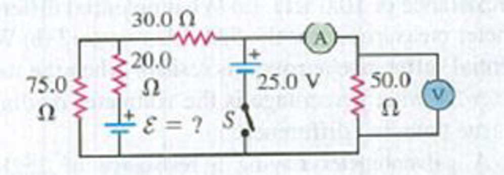
In the circuit shown in Fig. E26.31 the batteries have negligible internal resistance and the meters are both idealized. With the switch S open, the voltmeter reads 15.0 V. (a) Find the emf ε of the battery, (b) What will the ammeter read when the switch is closed?
Figure E26.31
Expert Solution & Answer
Want to see the full answer?
Check out a sample textbook solution
Students have asked these similar questions
Make sure to draw a Free Body Diagram as well
Make sure to draw a Free Body Diagram as well
Make sure to draw a Free Body Diagram please as well
Chapter 26 Solutions
University Physics (14th Edition)
Ch. 26 - In which 120-V light bulb does the filament have...Ch. 26 - Two 120-V light bulbs, one 25-W and one 200-W,...Ch. 26 - You connect a number of identical light bulbs to a...Ch. 26 - In the circuit shown in Fig. Q26.4, three...Ch. 26 - If two resistors R1 and R2 (R2 R1) are connected...Ch. 26 - If two resistors R1 and R2 (R2 R1) are connected...Ch. 26 - A battery with no internal resistance is connected...Ch. 26 - A resistor consists of three identical metal...Ch. 26 - A light bulb is connected in the circuit shown in...Ch. 26 - A real battery, having nonnegligible internal...
Ch. 26 - If the battery in Discussion Question Q26.10 is...Ch. 26 - Consider the circuit shown in Fig. Q26.12. What...Ch. 26 - Is it possible to connect resistors together in a...Ch. 26 - The battery in the circuit shown in Fig. Q26.14...Ch. 26 - In a two-cell flashlight, the batteries are...Ch. 26 - Identical light bulbs A, B, and C are connected as...Ch. 26 - The emf of a flashlight battery is roughly...Ch. 26 - Will the capacitors in the circuits shown in Fig....Ch. 26 - Verify that the time constant RC has units of...Ch. 26 - For very large resistances it is easy to construct...Ch. 26 - When a capacitor, battery, and resistor are...Ch. 26 - A uniform wire of resistance R is cut into three...Ch. 26 - A machine part has a resistor X protruding from an...Ch. 26 - A resistor with R1 = 25.0 is connected to a...Ch. 26 - A 42- resistor and a 20- resistor are connected in...Ch. 26 - A triangular array of resistors is shown in Fig....Ch. 26 - For the circuit shown in Fig. E26.6 both meters...Ch. 26 - For the circuit shown in Fig. E26.7 find the...Ch. 26 - Three resistors having resistances of 1.60 , 2.40...Ch. 26 - Now the three resistors of Exercise 26.8 are...Ch. 26 - Power Rating of a Resistor. The power rating of a...Ch. 26 - In Fig. E26.11, R1, = 3.00 , R2 = 6.00 , and R3=...Ch. 26 - In Fig. E26.11 the battery has emf 35.0 V and...Ch. 26 - Compute the equivalent resistance of the network...Ch. 26 - Compute the equivalent resistance of the network...Ch. 26 - In the circuit of Fig. E26.15, each resistor...Ch. 26 - Consider the circuit shown in Fig. E26.16. The...Ch. 26 - In the circuit shown in Fig. E26.17, the voltage...Ch. 26 - In the circuit shown in Fig. E26.18, = 36.0 V,...Ch. 26 - CP In the circuit in Fig. E26.19, a 20.0- resistor...Ch. 26 - In the circuit shown in Fig. E26.20, the rate at...Ch. 26 - Light Bulbs in Series and in Parallel. Two light...Ch. 26 - Light Bulbs in Series. A 60-W, 120-V light bulb...Ch. 26 - In the circuit shown in Fig. E26.23, ammeter A1...Ch. 26 - The batteries shown in the circuit in Fig. E26.24...Ch. 26 - In the circuit shown in Fig. E26.25 find (a) the...Ch. 26 - Find the emfs 1 and 2 in the circuit of Fig....Ch. 26 - In the circuit shown in Fig. E26.27, find (a) the...Ch. 26 - In the circuit shown in Fig. E26.28, find (a) the...Ch. 26 - The 10.00-V battery in Fig. E26.28 is removed from...Ch. 26 - The 5.00-V battery in Fig. E26.28 is removed from...Ch. 26 - In the circuit shown in Fig. E26.31 the batteries...Ch. 26 - In the circuit shown in Fig. E26.32 both batteries...Ch. 26 - In the circuit shown in Fig. E26.33 all meters are...Ch. 26 - In the circuit shown in Fig. E26.34, the 6.0-...Ch. 26 - The resistance of a galvanometer coil is 25.0 ,...Ch. 26 - The resistance of the coil of a pivoted coil...Ch. 26 - A circuit consists of a series combination of...Ch. 26 - A galvanometer having a resistance of 25.0 has a...Ch. 26 - A capacitor is charged to a potential of 12.0 V...Ch. 26 - You connect a battery, resistor, and capacitor as...Ch. 26 - A 4.60-F capacitor that is initially uncharged is...Ch. 26 - You connect a battery, resistor, and capacitor as...Ch. 26 - CP In the circuit shown in Fig. E26.43 both...Ch. 26 - A 12.4-F capacitor is connected through a 0.895-M...Ch. 26 - An emf source with = 120 V, a resistor with R =...Ch. 26 - A resistor and a capacitor are connected in series...Ch. 26 - CP In the circuit shown in Fig. E26.47 each...Ch. 26 - A 1.50-F capacitor is charging through a 12.0-...Ch. 26 - In the circuit in Fig. E26.49 the capacitors are...Ch. 26 - A 12.0-F capacitor is charged to a potential of...Ch. 26 - In the circuit shown in Fig. E26.51, C = 5.90 F, ...Ch. 26 - Prob. 26.52ECh. 26 - A 1500-W electric beater is plugged into the...Ch. 26 - In Fig. P26.54, the battery has negligible...Ch. 26 - The two identical light bulbs in Example 26.2...Ch. 26 - Each of the three resistors in Fig. P26.56 has a...Ch. 26 - (a) Find the potential of point a with respect to...Ch. 26 - CP For the circuit shown in Fig. P26.58 a 20.0-...Ch. 26 - Calculate the three currents I1, I2, and I3...Ch. 26 - What must the emf in Fig. P26.60 be in order for...Ch. 26 - Find the current through each of the three...Ch. 26 - (a) Find the current through the battery and each...Ch. 26 - Consider the circuit shown in Fig. P26.63. (a)...Ch. 26 - In the circuit shown in Fig. P26.64, = 24.0 V,...Ch. 26 - In the circuit shown in Fig. P26.65, the current...Ch. 26 - In the circuit shown in Fig. P26.66 all the...Ch. 26 - Figure P26.67 employs a convention often used in...Ch. 26 - Three identical resistors are connected in series....Ch. 26 - A resistor R1 consumes electrical power P1 when...Ch. 26 - The capacitor in Fig. F26.70 is initially...Ch. 26 - A 2.00-F capacitor that is initially uncharged is...Ch. 26 - A 6.00-F capacitor that is initially uncharged is...Ch. 26 - Point a in Fig. P26.73 is maintained at a constant...Ch. 26 - The Wheatstone Bridge. The circuit shown in Fig....Ch. 26 - (See Problem 26.67.) (a) What is the potential of...Ch. 26 - A 2.36-F capacitor that is initially uncharged is...Ch. 26 - A 224- resistor and a 589- resistor are connected...Ch. 26 - A resistor with R = 850 is connected to the...Ch. 26 - A capacitor that is initially uncharged is...Ch. 26 - DATA You set up the circuit shown in Fig. 26.22a,...Ch. 26 - DATA You set up the circuit shown in Fig. 26.20....Ch. 26 - DATA The electronics supply company where you work...Ch. 26 - An Infinite Network. As shown in Fig. P26.83, a...Ch. 26 - Suppose a resistor R lies along each edge of a...Ch. 26 - BIO Attenuator Chains and Axons. The infinite...Ch. 26 - Assume that a typical open ion channel spanning an...Ch. 26 - In a simple model of an axon conducting a nerve...Ch. 26 - Cell membranes across a wide variety of organisms...
Additional Science Textbook Solutions
Find more solutions based on key concepts
33. Consider the reaction:
The tabulated data were collected for the concentration of C4H8 as a function...
Chemistry: Structure and Properties (2nd Edition)
1. ___ Mitosis 2. ___ Meiosis 3. __ Homologous chromosomes 4. __ Crossing over 5. __ Cytokinesis A. Cytoplasmic...
Microbiology with Diseases by Body System (5th Edition)
Plants use the process of photosynthesis to convert the energy in sunlight to chemical energy in the form of su...
Campbell Essential Biology (7th Edition)
89. Determine the volume of 0.150 M NaOH solution required to neutralize each sample of hydrochloric acid. The ...
Introductory Chemistry (6th Edition)
Choose the best answer to each of the following. Explain your reasoning. The luminosity of a quasar is generate...
Cosmic Perspective Fundamentals
1.1 Write a one-sentence definition for each of the following:
a. chemistry
b. chemical
Chemistry: An Introduction to General, Organic, and Biological Chemistry (13th Edition)
Knowledge Booster


Learn more about
Need a deep-dive on the concept behind this application? Look no further. Learn more about this topic, physics and related others by exploring similar questions and additional content below.Similar questions
- please answer this asap!!!!arrow_forwardRT = 4.7E-30 18V IT = 2.3E-3A+ 12 38Ω ли 56Ω ли r5 27Ω ли r3 28Ω r4 > 75Ω r6 600 0.343V 75.8A Now figure out how much current in going through the r4 resistor. |4 = unit And then use that current to find the voltage drop across the r resistor. V4 = unitarrow_forward7 Find the volume inside the cone z² = x²+y², above the (x, y) plane, and between the spheres x²+y²+z² = 1 and x² + y²+z² = 4. Hint: use spherical polar coordinates.arrow_forward
- ганм Two long, straight wires are oriented perpendicular to the page, as shown in the figure(Figure 1). The current in one wire is I₁ = 3.0 A, pointing into the page, and the current in the other wire is 12 4.0 A, pointing out of the page. = Find the magnitude and direction of the net magnetic field at point P. Express your answer using two significant figures. VO ΜΕ ΑΣΦ ? Figure P 5.0 cm 5.0 cm ₁ = 3.0 A 12 = 4.0 A B: μΤ You have already submitted this answer. Enter a new answer. No credit lost. Try again. Submit Previous Answers Request Answer 1 of 1 Part B X Express your answer using two significant figures. ΜΕ ΑΣΦ 0 = 0 ? below the dashed line to the right P You have already submitted this answer. Enter a new answer. No credit lost. Try again.arrow_forwardAn infinitely long conducting cylindrical rod with a positive charge λ per unit length is surrounded by a conducting cylindrical shell (which is also infinitely long) with a charge per unit length of −2λ and radius r1, as shown in the figure. What is σinner, the surface charge density (charge per unit area) on the inner surface of the conducting shell? What is σouter, the surface charge density on the outside of the conducting shell? (Recall from the problem statement that the conducting shell has a total charge per unit length given by −2λ.)arrow_forwardA small conducting spherical shell with inner radius aa and outer radius b is concentric with a larger conducting spherical shell with inner radius c and outer radius d (Figure 1). The inner shell has total charge +2q, and the outer shell has charge −2q. What's the total charge on the inner surface of the small shell? What's the total charge on the outer surface of the small shell? What's the total charge on the inner surface of the large shell? What's the total charge on the outer surface of the large shell?arrow_forward
arrow_back_ios
SEE MORE QUESTIONS
arrow_forward_ios
Recommended textbooks for you
 Physics for Scientists and Engineers: Foundations...PhysicsISBN:9781133939146Author:Katz, Debora M.Publisher:Cengage Learning
 College PhysicsPhysicsISBN:9781305952300Author:Raymond A. Serway, Chris VuillePublisher:Cengage Learning
 College PhysicsPhysicsISBN:9781285737027Author:Raymond A. Serway, Chris VuillePublisher:Cengage Learning
 Physics for Scientists and Engineers, Technology ...PhysicsISBN:9781305116399Author:Raymond A. Serway, John W. JewettPublisher:Cengage Learning
 Principles of Physics: A Calculus-Based TextPhysicsISBN:9781133104261Author:Raymond A. Serway, John W. JewettPublisher:Cengage Learning
Physics for Scientists and Engineers: Foundations...
Physics
ISBN:9781133939146
Author:Katz, Debora M.
Publisher:Cengage Learning
College Physics
Physics
ISBN:9781305952300
Author:Raymond A. Serway, Chris Vuille
Publisher:Cengage Learning
College Physics
Physics
ISBN:9781285737027
Author:Raymond A. Serway, Chris Vuille
Publisher:Cengage Learning
Physics for Scientists and Engineers, Technology ...
Physics
ISBN:9781305116399
Author:Raymond A. Serway, John W. Jewett
Publisher:Cengage Learning
Principles of Physics: A Calculus-Based Text
Physics
ISBN:9781133104261
Author:Raymond A. Serway, John W. Jewett
Publisher:Cengage Learning
DC Series circuits explained - The basics working principle; Author: The Engineering Mindset;https://www.youtube.com/watch?v=VV6tZ3Aqfuc;License: Standard YouTube License, CC-BY