
University Physics (14th Edition)
14th Edition
ISBN: 9780133969290
Author: Hugh D. Young, Roger A. Freedman
Publisher: PEARSON
expand_more
expand_more
format_list_bulleted
Videos
Textbook Question
Chapter 26, Problem 26.19E
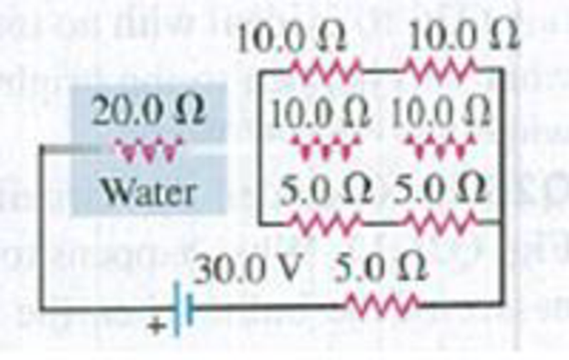
CP In the circuit in Fig. E26.19, a 20.0-Ω resistor is inside 100 g of pure water that is surrounded by insulating styrofoam. If the water is initially at 10.0°C, how long will it take for its temperature to rise to 58.0°C?
Figure E26.19
Expert Solution & Answer

Trending nowThis is a popular solution!

Students have asked these similar questions
A convex mirror (f.=-6.20cm) and a concave minor (f2=8.10 cm)
distance of 15.5cm
are facing each other and are separated by a
An object is placed between the mirrors and is 7.8cm from each
mirror. Consider the light from the object that reflects first from
the convex mirror and then from the concave mirror. What is the
distance of the image (dia) produced by the concave mirror?
cm.
An amusement park spherical mirror shows
park spherical mirror shows anyone who stands
2.80m in front of it an upright image
one
and a half times the
person's height. What is the focal length of the minor?
m.
An m = 69.0-kg person running at an initial speed of v = 4.50 m/s jumps onto an M = 138-kg cart initially at rest (figure below). The person slides on the cart's top surface and finally comes to rest relative to the cart. The coefficient of kinetic friction between the person and the cart is
0.440. Friction between the cart and ground can be ignored. (Let the positive direction be to the right.)
m
M
(a) Find the final velocity of the person and cart relative to the ground. (Indicate the direction with the sign of your answer.)
m/s
(b) Find the friction force acting on the person while he is sliding across the top surface of the cart. (Indicate the direction with the sign of your answer.)
N
(c) How long does the friction force act on the person?
S
(d) Find the change in momentum of the person. (Indicate the direction with the sign of your answer.)
N.S
Find the change in momentum of the cart. (Indicate the direction with the sign of your answer.)
N.S
(e) Determine the displacement of the…
Chapter 26 Solutions
University Physics (14th Edition)
Ch. 26 - In which 120-V light bulb does the filament have...Ch. 26 - Two 120-V light bulbs, one 25-W and one 200-W,...Ch. 26 - You connect a number of identical light bulbs to a...Ch. 26 - In the circuit shown in Fig. Q26.4, three...Ch. 26 - If two resistors R1 and R2 (R2 R1) are connected...Ch. 26 - If two resistors R1 and R2 (R2 R1) are connected...Ch. 26 - A battery with no internal resistance is connected...Ch. 26 - A resistor consists of three identical metal...Ch. 26 - A light bulb is connected in the circuit shown in...Ch. 26 - A real battery, having nonnegligible internal...
Ch. 26 - If the battery in Discussion Question Q26.10 is...Ch. 26 - Consider the circuit shown in Fig. Q26.12. What...Ch. 26 - Is it possible to connect resistors together in a...Ch. 26 - The battery in the circuit shown in Fig. Q26.14...Ch. 26 - In a two-cell flashlight, the batteries are...Ch. 26 - Identical light bulbs A, B, and C are connected as...Ch. 26 - The emf of a flashlight battery is roughly...Ch. 26 - Will the capacitors in the circuits shown in Fig....Ch. 26 - Verify that the time constant RC has units of...Ch. 26 - For very large resistances it is easy to construct...Ch. 26 - When a capacitor, battery, and resistor are...Ch. 26 - A uniform wire of resistance R is cut into three...Ch. 26 - A machine part has a resistor X protruding from an...Ch. 26 - A resistor with R1 = 25.0 is connected to a...Ch. 26 - A 42- resistor and a 20- resistor are connected in...Ch. 26 - A triangular array of resistors is shown in Fig....Ch. 26 - For the circuit shown in Fig. E26.6 both meters...Ch. 26 - For the circuit shown in Fig. E26.7 find the...Ch. 26 - Three resistors having resistances of 1.60 , 2.40...Ch. 26 - Now the three resistors of Exercise 26.8 are...Ch. 26 - Power Rating of a Resistor. The power rating of a...Ch. 26 - In Fig. E26.11, R1, = 3.00 , R2 = 6.00 , and R3=...Ch. 26 - In Fig. E26.11 the battery has emf 35.0 V and...Ch. 26 - Compute the equivalent resistance of the network...Ch. 26 - Compute the equivalent resistance of the network...Ch. 26 - In the circuit of Fig. E26.15, each resistor...Ch. 26 - Consider the circuit shown in Fig. E26.16. The...Ch. 26 - In the circuit shown in Fig. E26.17, the voltage...Ch. 26 - In the circuit shown in Fig. E26.18, = 36.0 V,...Ch. 26 - CP In the circuit in Fig. E26.19, a 20.0- resistor...Ch. 26 - In the circuit shown in Fig. E26.20, the rate at...Ch. 26 - Light Bulbs in Series and in Parallel. Two light...Ch. 26 - Light Bulbs in Series. A 60-W, 120-V light bulb...Ch. 26 - In the circuit shown in Fig. E26.23, ammeter A1...Ch. 26 - The batteries shown in the circuit in Fig. E26.24...Ch. 26 - In the circuit shown in Fig. E26.25 find (a) the...Ch. 26 - Find the emfs 1 and 2 in the circuit of Fig....Ch. 26 - In the circuit shown in Fig. E26.27, find (a) the...Ch. 26 - In the circuit shown in Fig. E26.28, find (a) the...Ch. 26 - The 10.00-V battery in Fig. E26.28 is removed from...Ch. 26 - The 5.00-V battery in Fig. E26.28 is removed from...Ch. 26 - In the circuit shown in Fig. E26.31 the batteries...Ch. 26 - In the circuit shown in Fig. E26.32 both batteries...Ch. 26 - In the circuit shown in Fig. E26.33 all meters are...Ch. 26 - In the circuit shown in Fig. E26.34, the 6.0-...Ch. 26 - The resistance of a galvanometer coil is 25.0 ,...Ch. 26 - The resistance of the coil of a pivoted coil...Ch. 26 - A circuit consists of a series combination of...Ch. 26 - A galvanometer having a resistance of 25.0 has a...Ch. 26 - A capacitor is charged to a potential of 12.0 V...Ch. 26 - You connect a battery, resistor, and capacitor as...Ch. 26 - A 4.60-F capacitor that is initially uncharged is...Ch. 26 - You connect a battery, resistor, and capacitor as...Ch. 26 - CP In the circuit shown in Fig. E26.43 both...Ch. 26 - A 12.4-F capacitor is connected through a 0.895-M...Ch. 26 - An emf source with = 120 V, a resistor with R =...Ch. 26 - A resistor and a capacitor are connected in series...Ch. 26 - CP In the circuit shown in Fig. E26.47 each...Ch. 26 - A 1.50-F capacitor is charging through a 12.0-...Ch. 26 - In the circuit in Fig. E26.49 the capacitors are...Ch. 26 - A 12.0-F capacitor is charged to a potential of...Ch. 26 - In the circuit shown in Fig. E26.51, C = 5.90 F, ...Ch. 26 - Prob. 26.52ECh. 26 - A 1500-W electric beater is plugged into the...Ch. 26 - In Fig. P26.54, the battery has negligible...Ch. 26 - The two identical light bulbs in Example 26.2...Ch. 26 - Each of the three resistors in Fig. P26.56 has a...Ch. 26 - (a) Find the potential of point a with respect to...Ch. 26 - CP For the circuit shown in Fig. P26.58 a 20.0-...Ch. 26 - Calculate the three currents I1, I2, and I3...Ch. 26 - What must the emf in Fig. P26.60 be in order for...Ch. 26 - Find the current through each of the three...Ch. 26 - (a) Find the current through the battery and each...Ch. 26 - Consider the circuit shown in Fig. P26.63. (a)...Ch. 26 - In the circuit shown in Fig. P26.64, = 24.0 V,...Ch. 26 - In the circuit shown in Fig. P26.65, the current...Ch. 26 - In the circuit shown in Fig. P26.66 all the...Ch. 26 - Figure P26.67 employs a convention often used in...Ch. 26 - Three identical resistors are connected in series....Ch. 26 - A resistor R1 consumes electrical power P1 when...Ch. 26 - The capacitor in Fig. F26.70 is initially...Ch. 26 - A 2.00-F capacitor that is initially uncharged is...Ch. 26 - A 6.00-F capacitor that is initially uncharged is...Ch. 26 - Point a in Fig. P26.73 is maintained at a constant...Ch. 26 - The Wheatstone Bridge. The circuit shown in Fig....Ch. 26 - (See Problem 26.67.) (a) What is the potential of...Ch. 26 - A 2.36-F capacitor that is initially uncharged is...Ch. 26 - A 224- resistor and a 589- resistor are connected...Ch. 26 - A resistor with R = 850 is connected to the...Ch. 26 - A capacitor that is initially uncharged is...Ch. 26 - DATA You set up the circuit shown in Fig. 26.22a,...Ch. 26 - DATA You set up the circuit shown in Fig. 26.20....Ch. 26 - DATA The electronics supply company where you work...Ch. 26 - An Infinite Network. As shown in Fig. P26.83, a...Ch. 26 - Suppose a resistor R lies along each edge of a...Ch. 26 - BIO Attenuator Chains and Axons. The infinite...Ch. 26 - Assume that a typical open ion channel spanning an...Ch. 26 - In a simple model of an axon conducting a nerve...Ch. 26 - Cell membranes across a wide variety of organisms...
Additional Science Textbook Solutions
Find more solutions based on key concepts
What is meant by high-throughput in culturing microorganisms? How has it benefited microbiology?
Brock Biology of Microorganisms (15th Edition)
Match each of the following items with all the terms it applies to:
Human Physiology: An Integrated Approach (8th Edition)
1.3 Obtain a bottle of multivitamins and read the list of ingredients. What are four chemicals from the list?
Chemistry: An Introduction to General, Organic, and Biological Chemistry (13th Edition)
Compare each of the mechanisms listed here with the mechanism for each of the two parts of the acid-catalyzed h...
Organic Chemistry (8th Edition)
Choose the best answer to each of the following. Explain your reasoning. Tycho Brahes contributions to astronom...
Cosmic Perspective Fundamentals
Use the following graph to answer questions 3 and 4. 3. Which of the lines best depicts the log phase of a ther...
Microbiology: An Introduction
Knowledge Booster


Learn more about
Need a deep-dive on the concept behind this application? Look no further. Learn more about this topic, physics and related others by exploring similar questions and additional content below.Similar questions
- Small ice cubes, each of mass 5.60 g, slide down a frictionless track in a steady stream, as shown in the figure below. Starting from rest, each cube moves down through a net vertical distance of h = 1.50 m and leaves the bottom end of the track at an angle of 40.0° above the horizontal. At the highest point of its subsequent trajectory, the cube strikes a vertical wall and rebounds with half the speed it had upon impact. If 10 cubes strike the wall per second, what average force is exerted upon the wall? N ---direction--- ▾ ---direction--- to the top to the bottom to the left to the right 1.50 m 40.0°arrow_forwardThe magnitude of the net force exerted in the x direction on a 3.00-kg particle varies in time as shown in the figure below. F(N) 4 3 A 2 t(s) 1 2 3 45 (a) Find the impulse of the force over the 5.00-s time interval. == N⚫s (b) Find the final velocity the particle attains if it is originally at rest. m/s (c) Find its final velocity if its original velocity is -3.50 î m/s. V₁ m/s (d) Find the average force exerted on the particle for the time interval between 0 and 5.00 s. = avg Narrow_forward••63 SSM www In the circuit of Fig. 27-65, 8 = 1.2 kV, C = 6.5 µF, R₁ S R₂ R3 800 C H R₁ = R₂ = R3 = 0.73 MQ. With C completely uncharged, switch S is suddenly closed (at t = 0). At t = 0, what are (a) current i̟ in resistor 1, (b) current 2 in resistor 2, and (c) current i3 in resistor 3? At t = ∞o (that is, after many time constants), what are (d) i₁, (e) i₂, and (f) iz? What is the potential difference V2 across resistor 2 at (g) t = 0 and (h) t = ∞o? (i) Sketch V2 versus t between these two extreme times. Figure 27-65 Problem 63.arrow_forward
- Thor flies by spinning his hammer really fast from a leather strap at the end of the handle, letting go, then grabbing it and having it pull him. If Thor wants to reach escape velocity (velocity needed to leave Earth’s atmosphere), he will need the linear velocity of the center of mass of the hammer to be 11,200 m/s. Thor's escape velocity is 33532.9 rad/s, the angular velocity is 8055.5 rad/s^2. While the hammer is spinning at its maximum speed what impossibly large tension does the leather strap, which the hammer is spinning by, exert when the hammer is at its lowest point? the hammer has a total mass of 20.0kg.arrow_forwardIf the room’s radius is 16.2 m, at what minimum linear speed does Quicksilver need to run to stay on the walls without sliding down? Assume the coefficient of friction between Quicksilver and the wall is 0.236.arrow_forwardIn the comics Thor flies by spinning his hammer really fast from a leather strap at the end of the handle, letting go, then grabbing it and having it pull him. If Thor wants to reach escape velocity (velocity needed to leave Earth’s atmosphere), he will need the linear velocity of the center of mass of the hammer to be 11,200 m/s. A) If the distance from the end of the strap to the center of the hammer is 0.334 m, what angular velocity does Thor need to spin his hammer at to reach escape velocity? b) If the hammer starts from rest what angular acceleration does Thor need to reach that angular velocity in 4.16 s? c) While the hammer is spinning at its maximum speed what impossibly large tension does the leather strap, which the hammer is spinning by, exert when the hammer is at its lowest point? The hammer has a total mass of 20.0kg.arrow_forward
- The car goes from driving straight to spinning at 10.6 rev/min in 0.257 s with a radius of 12.2 m. The angular accleration is 4.28 rad/s^2. During this flip Barbie stays firmly seated in the car’s seat. Barbie has a mass of 58.0 kg, what is her normal force at the top of the loop?arrow_forwardConsider a hoop of radius R and mass M rolling without slipping. Which form of kinetic energy is larger, translational or rotational?arrow_forwardA roller-coaster vehicle has a mass of 571 kg when fully loaded with passengers (see figure). A) If the vehicle has a speed of 22.5 m/s at point A, what is the force of the track on the vehicle at this point? B) What is the maximum speed the vehicle can have at point B, in order for gravity to hold it on the track?arrow_forward
- This one wheeled motorcycle’s wheel maximum angular velocity was about 430 rev/min. Given that it’s radius was 0.920 m, what was the largest linear velocity of the monowheel?The monowheel could not accelerate fast or the rider would start spinning inside (this is called "gerbiling"). The maximum angular acceleration was 10.9 rad/s2. How long, in seconds, would it take it to hit maximum speed from rest?arrow_forwardIf points a and b are connected by a wire with negligible resistance, find the magnitude of the current in the 12.0 V battery.arrow_forwardConsider the two pucks shown in the figure. As they move towards each other, the momentum of each puck is equal in magnitude and opposite in direction. Given that v kinetic energy of the system is converted to internal energy? 30.0° 130.0 = green 11.0 m/s, and m blue is 25.0% greater than m 'green' what are the final speeds of each puck (in m/s), if 1½-½ t thearrow_forward
arrow_back_ios
SEE MORE QUESTIONS
arrow_forward_ios
Recommended textbooks for you

 Physics for Scientists and EngineersPhysicsISBN:9781337553278Author:Raymond A. Serway, John W. JewettPublisher:Cengage Learning
 Physics for Scientists and Engineers with Modern ...PhysicsISBN:9781337553292Author:Raymond A. Serway, John W. JewettPublisher:Cengage Learning
 Principles of Physics: A Calculus-Based TextPhysicsISBN:9781133104261Author:Raymond A. Serway, John W. JewettPublisher:Cengage Learning
 Physics for Scientists and Engineers: Foundations...PhysicsISBN:9781133939146Author:Katz, Debora M.Publisher:Cengage Learning
 College PhysicsPhysicsISBN:9781938168000Author:Paul Peter Urone, Roger HinrichsPublisher:OpenStax College
Physics for Scientists and Engineers
Physics
ISBN:9781337553278
Author:Raymond A. Serway, John W. Jewett
Publisher:Cengage Learning
Physics for Scientists and Engineers with Modern ...
Physics
ISBN:9781337553292
Author:Raymond A. Serway, John W. Jewett
Publisher:Cengage Learning
Principles of Physics: A Calculus-Based Text
Physics
ISBN:9781133104261
Author:Raymond A. Serway, John W. Jewett
Publisher:Cengage Learning
Physics for Scientists and Engineers: Foundations...
Physics
ISBN:9781133939146
Author:Katz, Debora M.
Publisher:Cengage Learning
College Physics
Physics
ISBN:9781938168000
Author:Paul Peter Urone, Roger Hinrichs
Publisher:OpenStax College
DC Series circuits explained - The basics working principle; Author: The Engineering Mindset;https://www.youtube.com/watch?v=VV6tZ3Aqfuc;License: Standard YouTube License, CC-BY