
Videos
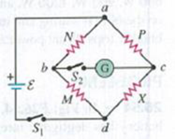
The Wheatstone Bridge. The circuit shown in Fig. P26.74, called a Wheatstone bridge, is used to determine the value of an unknown resistor X by comparison with three resistors M, N, and P whose resistances can be varied. For each setting, the resistance of each resistor is precisely known. With switches S1 and S2 closed, these resistors are varied until the current in the galvanometer G is zero; the bridge is then said to be balanced. (a) Show that under this condition the unknown resistance is given by X = MP/N. (This method permits very high precision in comparing resistors.) (b) If galvanometer G shows zero deflection when M = 850.0 Ω, N = 15.00 Ω, and P = 33.48 Ω, what is the unknown resistance X?
Figure P26.74
Want to see the full answer?
Check out a sample textbook solution
Chapter 26 Solutions
University Physics (14th Edition)
Additional Science Textbook Solutions
Campbell Essential Biology (7th Edition)
Human Physiology: An Integrated Approach (8th Edition)
Concepts of Genetics (12th Edition)
Organic Chemistry (8th Edition)
Chemistry: An Introduction to General, Organic, and Biological Chemistry (13th Edition)
Applications and Investigations in Earth Science (9th Edition)


- Make sure to draw a sketch and a free body diagram. DO NOT give me examples but ONLY the solutionarrow_forwardMake sure to draw a sketch AND draw a Free body diagramarrow_forwardP -3 ft 3 ft. O A B 1.5 ft Do 1.5 ft ✓ For the frame and loading shown, determine the magnitude of the reaction at C (in lb) if P = 55 lb. (Hint: Use the special cases: Two-force body and Three-force body.)arrow_forward
- A convex mirror (f.=-6.20cm) and a concave minor (f2=8.10 cm) distance of 15.5cm are facing each other and are separated by a An object is placed between the mirrors and is 7.8cm from each mirror. Consider the light from the object that reflects first from the convex mirror and then from the concave mirror. What is the distance of the image (dia) produced by the concave mirror? cm.arrow_forwardAn amusement park spherical mirror shows park spherical mirror shows anyone who stands 2.80m in front of it an upright image one and a half times the person's height. What is the focal length of the minor? m.arrow_forwardAn m = 69.0-kg person running at an initial speed of v = 4.50 m/s jumps onto an M = 138-kg cart initially at rest (figure below). The person slides on the cart's top surface and finally comes to rest relative to the cart. The coefficient of kinetic friction between the person and the cart is 0.440. Friction between the cart and ground can be ignored. (Let the positive direction be to the right.) m M (a) Find the final velocity of the person and cart relative to the ground. (Indicate the direction with the sign of your answer.) m/s (b) Find the friction force acting on the person while he is sliding across the top surface of the cart. (Indicate the direction with the sign of your answer.) N (c) How long does the friction force act on the person? S (d) Find the change in momentum of the person. (Indicate the direction with the sign of your answer.) N.S Find the change in momentum of the cart. (Indicate the direction with the sign of your answer.) N.S (e) Determine the displacement of the…arrow_forward
- Small ice cubes, each of mass 5.60 g, slide down a frictionless track in a steady stream, as shown in the figure below. Starting from rest, each cube moves down through a net vertical distance of h = 1.50 m and leaves the bottom end of the track at an angle of 40.0° above the horizontal. At the highest point of its subsequent trajectory, the cube strikes a vertical wall and rebounds with half the speed it had upon impact. If 10 cubes strike the wall per second, what average force is exerted upon the wall? N ---direction--- ▾ ---direction--- to the top to the bottom to the left to the right 1.50 m 40.0°arrow_forwardThe magnitude of the net force exerted in the x direction on a 3.00-kg particle varies in time as shown in the figure below. F(N) 4 3 A 2 t(s) 1 2 3 45 (a) Find the impulse of the force over the 5.00-s time interval. == N⚫s (b) Find the final velocity the particle attains if it is originally at rest. m/s (c) Find its final velocity if its original velocity is -3.50 î m/s. V₁ m/s (d) Find the average force exerted on the particle for the time interval between 0 and 5.00 s. = avg Narrow_forward••63 SSM www In the circuit of Fig. 27-65, 8 = 1.2 kV, C = 6.5 µF, R₁ S R₂ R3 800 C H R₁ = R₂ = R3 = 0.73 MQ. With C completely uncharged, switch S is suddenly closed (at t = 0). At t = 0, what are (a) current i̟ in resistor 1, (b) current 2 in resistor 2, and (c) current i3 in resistor 3? At t = ∞o (that is, after many time constants), what are (d) i₁, (e) i₂, and (f) iz? What is the potential difference V2 across resistor 2 at (g) t = 0 and (h) t = ∞o? (i) Sketch V2 versus t between these two extreme times. Figure 27-65 Problem 63.arrow_forward
- Thor flies by spinning his hammer really fast from a leather strap at the end of the handle, letting go, then grabbing it and having it pull him. If Thor wants to reach escape velocity (velocity needed to leave Earth’s atmosphere), he will need the linear velocity of the center of mass of the hammer to be 11,200 m/s. Thor's escape velocity is 33532.9 rad/s, the angular velocity is 8055.5 rad/s^2. While the hammer is spinning at its maximum speed what impossibly large tension does the leather strap, which the hammer is spinning by, exert when the hammer is at its lowest point? the hammer has a total mass of 20.0kg.arrow_forwardIf the room’s radius is 16.2 m, at what minimum linear speed does Quicksilver need to run to stay on the walls without sliding down? Assume the coefficient of friction between Quicksilver and the wall is 0.236.arrow_forwardIn the comics Thor flies by spinning his hammer really fast from a leather strap at the end of the handle, letting go, then grabbing it and having it pull him. If Thor wants to reach escape velocity (velocity needed to leave Earth’s atmosphere), he will need the linear velocity of the center of mass of the hammer to be 11,200 m/s. A) If the distance from the end of the strap to the center of the hammer is 0.334 m, what angular velocity does Thor need to spin his hammer at to reach escape velocity? b) If the hammer starts from rest what angular acceleration does Thor need to reach that angular velocity in 4.16 s? c) While the hammer is spinning at its maximum speed what impossibly large tension does the leather strap, which the hammer is spinning by, exert when the hammer is at its lowest point? The hammer has a total mass of 20.0kg.arrow_forward
 Physics for Scientists and Engineers, Technology ...PhysicsISBN:9781305116399Author:Raymond A. Serway, John W. JewettPublisher:Cengage Learning
 Physics for Scientists and Engineers: Foundations...PhysicsISBN:9781133939146Author:Katz, Debora M.Publisher:Cengage Learning
 Principles of Physics: A Calculus-Based TextPhysicsISBN:9781133104261Author:Raymond A. Serway, John W. JewettPublisher:Cengage Learning
 College PhysicsPhysicsISBN:9781305952300Author:Raymond A. Serway, Chris VuillePublisher:Cengage Learning
 College PhysicsPhysicsISBN:9781285737027Author:Raymond A. Serway, Chris VuillePublisher:Cengage Learning