
Concept explainers
Videos
Two steel bars (Es = 200 GPa and αs = 11.7 × 10⁻⁶/°C) are used to reinforce a brass bar (Eb =105 GPa, αb = 20.9 × 10⁻⁶/°C) that is subjected to a load P = 25 kN. When the steel bars were fabricated; the distance between the centers of the holes that were to fit on the pins was made 0.5 mm smaller than the 2 m needed. The steel bars were then placed in an oven to increase their length so that they would just fit on the pins. Following fabrication, the temperature in the steel bars dropped back to room temperature. Determine (a) the increase in temperature that was required to fit the steel bars on the pins, (b) the stress in the brass bar after the load is applied to it.
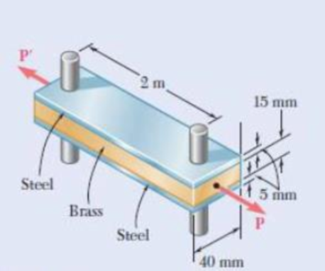
Fig. P2.55
(a)
The required temperature increment to fit the steel bars on the pins.
Answer to Problem 55P
The required temperature increment to fit the steel bars on the pins is
Explanation of Solution
Given information:
The magnitude of load
The coefficient
The coefficient
The young’s modulus
The young’s modulus
Determine the temperature change require to expand steel bar by this amount.
Here,
Substitute
Thus, the required temperature increment to fit the steel bars on the pins is
(b)
The normal stress in the brass bar after load applied.
Answer to Problem 55P
The normal stress due to steel is
The normal stress due to brass is
Explanation of Solution
Calculation:
After the assembly of the bars, a compressive force is developed in the brass bars and a tensile force is developed in the steel bars.
Determine the area
Here, b is the width of the steel bar , d is the depth of the steel bar, and t is the thickness of the bar.
Substitute
Determine the deformation of steel
Here, F is the compressive force, L is the length of the bar, and
Substitute
Determine the area
Here, b is the width of the brass bar, d is the depth of the brass bar.
Substitute
Determine the deformation of brass
Here,
Substitute
The deformation of bar and steel is equal to the initial amount of misfit.
Here,
Substitute
Find the stresses due to fabrication for steel using the relation:
Substitute
Find the stresses due to fabrication for brass using the relation:
Substitute
The stresses should be added the stress due to the
Consider
Find the force developed in steel bar
Substitute
Find the force developed in brass bar
Substitute
Find the force P as follows:
Here,
Substitute
Substitute
Substitute
Find the normal stress
Substitute
Find the normal stress
Substitute
The stress due to fabrication added.
Find the total stress using the relation:
Here,
Substitute
Thus, the normal stress due to steel is
Find the total stress using the relation:
Substitute
Thus, the normal stress due to brass is
Want to see more full solutions like this?
Chapter 2 Solutions
EBK MECHANICS OF MATERIALS


- Problem (14): A pump is being used to lift water from an underground tank through a pipe of diameter (d) at discharge (Q). The total head loss until the pump entrance can be calculated as (h₁ = K[V²/2g]), h where (V) is the flow velocity in the pipe. The elevation difference between the pump and tank surface is (h). Given the values of h [cm], d [cm], and K [-], calculate the maximum discharge Q [Lit/s] beyond which cavitation would take place at the pump entrance. Assume Turbulent flow conditions. Givens: h = 120.31 cm d = 14.455 cm K = 8.976 Q Answers: (1) 94.917 lit/s (2) 49.048 lit/s ( 3 ) 80.722 lit/s 68.588 lit/s 4arrow_forwardProblem (13): A pump is being used to lift water from the bottom tank to the top tank in a galvanized iron pipe at a discharge (Q). The length and diameter of the pipe section from the bottom tank to the pump are (L₁) and (d₁), respectively. The length and diameter of the pipe section from the pump to the top tank are (L2) and (d2), respectively. Given the values of Q [L/s], L₁ [m], d₁ [m], L₂ [m], d₂ [m], calculate total head loss due to friction (i.e., major loss) in the pipe (hmajor-loss) in [cm]. Givens: L₁,d₁ Pump L₂,d2 오 0.533 lit/s L1 = 6920.729 m d1 = 1.065 m L2 = 70.946 m d2 0.072 m Answers: (1) 3.069 cm (2) 3.914 cm ( 3 ) 2.519 cm ( 4 ) 1.855 cm TABLE 8.1 Equivalent Roughness for New Pipes Pipe Riveted steel Concrete Wood stave Cast iron Galvanized iron Equivalent Roughness, & Feet Millimeters 0.003-0.03 0.9-9.0 0.001-0.01 0.3-3.0 0.0006-0.003 0.18-0.9 0.00085 0.26 0.0005 0.15 0.045 0.000005 0.0015 0.0 (smooth) 0.0 (smooth) Commercial steel or wrought iron 0.00015 Drawn…arrow_forwardThe flow rate is 12.275 Liters/s and the diameter is 6.266 cm.arrow_forward
- An experimental setup is being built to study the flow in a large water main (i.e., a large pipe). The water main is expected to convey a discharge (Qp). The experimental tube will be built at a length scale of 1/20 of the actual water main. After building the experimental setup, the pressure drop per unit length in the model tube (APm/Lm) is measured. Problem (20): Given the value of APm/Lm [kPa/m], and assuming pressure coefficient similitude, calculate the drop in the pressure per unit length of the water main (APP/Lp) in [Pa/m]. Givens: AP M/L m = 590.637 kPa/m meen Answers: ( 1 ) 59.369 Pa/m ( 2 ) 73.83 Pa/m (3) 95.443 Pa/m ( 4 ) 44.444 Pa/m *******arrow_forwardFind the reaction force in y if Ain = 0.169 m^2, Aout = 0.143 m^2, p_in = 0.552 atm, Q = 0.367 m^3/s, α = 31.72 degrees. The pipe is flat on the ground so do not factor in weight of the pipe and fluid.arrow_forwardFind the reaction force in x if Ain = 0.301 m^2, Aout = 0.177 m^2, p_in = 1.338 atm, Q = 0.669 m^3/s, and α = 37.183 degreesarrow_forward
- Problem 5: Three-Force Equilibrium A structural connection at point O is in equilibrium under the action of three forces. • • . Member A applies a force of 9 kN vertically upward along the y-axis. Member B applies an unknown force F at the angle shown. Member C applies an unknown force T along its length at an angle shown. Determine the magnitudes of forces F and T required for equilibrium, assuming 0 = 90° y 9 kN Aarrow_forwardProblem 19: Determine the force in members HG, HE, and DE of the truss, and state if the members are in tension or compression. 4 ft K J I H G B C D E F -3 ft -3 ft 3 ft 3 ft 3 ft- 1500 lb 1500 lb 1500 lb 1500 lb 1500 lbarrow_forwardProblem 14: Determine the reactions at the pin A, and the tension in cord. Neglect the thickness of the beam. F1=26kN F2 13 12 80° -2m 3marrow_forward
- Problem 22: Determine the force in members GF, FC, and CD of the bridge truss and state if the members are in tension or compression. F 15 ft B D -40 ft 40 ft -40 ft 40 ft- 5 k 10 k 15 k 30 ft Earrow_forwardProblem 20: Determine the force in members BC, HC, and HG. After the truss is sectioned use a single equation of equilibrium for the calculation of each force. State if the members are in tension or compression. 5 kN 4 kN 4 kN 3 kN 2 kN B D E F 3 m -5 m- -5 m- 5 m 5 m-arrow_forwardAn experimental setup is being built to study the flow in a large water main (i.e., a large pipe). The water main is expected to convey a discharge (Qp). The experimental tube will be built at a length scale of 1/20 of the actual water main. After building the experimental setup, the pressure drop per unit length in the model tube (APm/Lm) is measured. Problem (19): Given the value of Qp [m³/s], and assuming Reynolds number similitude between the water main and experimental tube, calculate the flow rate in the model tube (Qm) in [lit/s]. = 30.015 m^3/sarrow_forward
 Mechanics of Materials (MindTap Course List)Mechanical EngineeringISBN:9781337093347Author:Barry J. Goodno, James M. GerePublisher:Cengage Learning