
Concept explainers
Videos
Both portions of the rod ABC are made of an aluminum for which E = 70 GPa. Knowing that the magnitude of P is 4 kN, determine (a) the value of Q so that the deflection at A is zero, (b) the corresponding deflection of B.
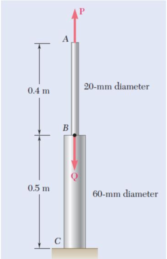
Fig. P2.19 and P2.20
a)
The value of (Q) when the deflection at A is zero.
Answer to Problem 19P
The value of (Q) when the deflection at A is zero is
Explanation of Solution
Given information:
The Young’s modulus of the aluminium (E) is
The force at the point A (P) is
The force at the point B is Q.
The diameter of the rod AB
The diameter of the rod BC
The length of the rod AB
The length of the rod BC
Calculation:
Calculate the cross-sectional area of the rod AB
Substitute
Calculate the cross-sectional area of the rod BC
Substitute
Calculate the defection of the rod AB
Substitute
Calculate the defection of the rod BC
Substitute
Calculate the force at the point B (Q):
Substitute
Hence, the value of (Q) when the deflection at A is zero is
b)
The deflection of B
Answer to Problem 19P
The deflection of B
Explanation of Solution
Given information:
The Young’s modulus of the aluminium (E) is
The force at the point A (P) is
The force at the point B is Q.
The diameter of the rod AB
The diameter of the rod BC
The length of the rod AB
The length of the rod BC
Calculation:
Calculate the cross-sectional area of the rod AB
Substitute
Calculate the cross-sectional area of the rod BC
Substitute
Calculate the defection of the rod AB
Substitute
Calculate the defection of the rod BC
Substitute
Calculate the force at the point B (Q):
Substitute
Calculate the deflection of B
Substitute
Hence, the deflection of B
Want to see more full solutions like this?
Chapter 2 Solutions
EBK MECHANICS OF MATERIALS


- My ID#016948724 please solve this problems and show me every step clear to follow pleasearrow_forwardMy ID# 016948724arrow_forwardPlease do not use any AI tools to solve this question. I need a fully manual, step-by-step solution with clear explanations, as if it were done by a human tutor. No AI-generated responses, please.arrow_forward
- Please do not use any AI tools to solve this question. I need a fully manual, step-by-step solution with clear explanations, as if it were done by a human tutor. No AI-generated responses, please.arrow_forwardPlease do not use any AI tools to solve this question. I need a fully manual, step-by-step solution with clear explanations, as if it were done by a human tutor. No AI-generated responses, please.arrow_forward[Q2]: The cost information supplied by the cost accountant is as follows:Sales 20,00 units, $ 10 per unitCalculate the (a/ newsale guantity and (b) new selling price to earn the sameVariable cost $ 6 per unit, Fixed Cost $ 30,000, Profit $ 50,000profit ifi) Variable cost increases by $ 2 per unitil) Fixed cost increase by $ 10,000Ili) Variable cost increase by $ 1 per unit and fixed cost reduces by $ 10,000arrow_forward
- can you please help me perform Visual Inspection and Fractography of the attatched image: Preliminary examination to identify the fracture origin, suspected fatigue striation, and corrosion evidences.arrow_forwardcan you please help[ me conduct Causal Analysis (FTA) on the scenario attatched: FTA diagram which is a fault tree analysis diagram will be used to gain an overview of the entire path of failure from root cause to the top event (i.e., the swing’s detachment) and to identify interactions between misuse, material decay and inspection errors.arrow_forwardhi can you please help me in finding the stress intensity factor using a k-calcluator for the scenario attathced in the images.arrow_forward
 Elements Of ElectromagneticsMechanical EngineeringISBN:9780190698614Author:Sadiku, Matthew N. O.Publisher:Oxford University Press
 Mechanics of Materials (10th Edition)Mechanical EngineeringISBN:9780134319650Author:Russell C. HibbelerPublisher:PEARSON
 Thermodynamics: An Engineering ApproachMechanical EngineeringISBN:9781259822674Author:Yunus A. Cengel Dr., Michael A. BolesPublisher:McGraw-Hill Education
 Control Systems EngineeringMechanical EngineeringISBN:9781118170519Author:Norman S. NisePublisher:WILEY
 Mechanics of Materials (MindTap Course List)Mechanical EngineeringISBN:9781337093347Author:Barry J. Goodno, James M. GerePublisher:Cengage Learning
 Engineering Mechanics: StaticsMechanical EngineeringISBN:9781118807330Author:James L. Meriam, L. G. Kraige, J. N. BoltonPublisher:WILEY