
INTERNATIONAL EDITION---Engineering Mechanics: Statics, 14th edition (SI unit)
14th Edition
ISBN: 9780133918922
Author: Russell C. Hibbeler
Publisher: PEARSON
expand_more
expand_more
format_list_bulleted
Videos
Textbook Question
Chapter 2.3, Problem 10P
Determine the magnitude of the resultant force and its direction, measured counterclockwise from the positive x axis.
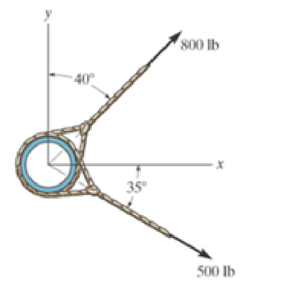
Prob. 2-10
Expert Solution & Answer

Learn your wayIncludes step-by-step video

schedule07:16
Students have asked these similar questions
M16x2 grade 8.8 bolts No. 25 C1-
Q.2. The figure is a cross section of a grade 25 cast-iron pressure vessel. A
total of N, M16x2.0 grade 8.8 bolts are to be used to resist a separating
force of 160 kN. (a) Determine ks, km, and C. (b) Find the number of bolts
required for a load factor of 2 where the bolts may be reused when the joint 19 mm
is taken apart. (c) with the number of bolts obtained in (b), determine the
realized load factor for overload, the yielding factor of safety, and the
separation factor of safety.
19 mm
Problem4.
The thin uniform disk of mass m = 1-kg and radius R = 0.1m spins about the bent shaft OG with
the angular speed w2 = 20 rad/s. At the same time, the shaft rotates about the z-axis with the angular
speed 001 = 10 rad/s. The angle between the bent portion of the shaft and the z-axis is ẞ = 35°. The
mass of the shaft is negligible compared to the mass of the disk.
a. Find the angular momentum of the disk with respect to point G, based on the axis
orientation as shown. Include an MVD in your solution.
b. Find the angular momentum of the disk with respect to point O, based on the axis
orientation as shown. (Note: O is NOT the center of fixed-point rotation.)
c. Find the kinetic energy of the assembly.
z
R
R
002
2R
x
Answer: H = -0.046ĵ-0.040 kg-m²/sec
Ho=-0.146-0.015 kg-m²/sec
T 0.518 N-m
=
Problem 3.
The assembly shown consists of a solid sphere of mass m and the uniform slender rod of the same
mass, both of which are welded to the shaft. The assembly is rotating with angular velocity w at a
particular moment. Find the angular momentum with respect to point O, in terms of the axes
shown.
Answer: Ñ。 = ½mc²wcosßsinßĵ + (}{mr²w + 2mb²w + ½ mc²wcos²ß) k
3
m
r
b
2
C
لا
m
Chapter 2 Solutions
INTERNATIONAL EDITION---Engineering Mechanics: Statics, 14th edition (SI unit)
Ch. 2.3 - Then establish the triangle rule, where FR = F1 +...Ch. 2.3 - Then establish the triangle rule to show FR = FU +...Ch. 2.3 - Determine the magnitude of the resultant force...Ch. 2.3 - Determine the magnitude of the resultant force....Ch. 2.3 - Determine the magnitude of the resultant force and...Ch. 2.3 - Resolve the 30-lb force into components along the...Ch. 2.3 - Resolve this force into components acting along...Ch. 2.3 - along the v axis. Prob. F2-6Ch. 2.3 - If = 60 and F = 450 N, determine the magnitude of...Ch. 2.3 - If the magnitude of the resultant force is to be...
Ch. 2.3 - Determine the magnitude of the resultant force FR...Ch. 2.3 - Determine the magnitudes of the two components of...Ch. 2.3 - Solve with F = 350 lb. Prob. 2-4/5Ch. 2.3 - Determine the magnitude of the resultant force FR...Ch. 2.3 - Resolve the force F1 into components acting along...Ch. 2.3 - Resolve the force F2 into components acting along...Ch. 2.3 - If the resultant force acting on the support is to...Ch. 2.3 - Determine the magnitude of the resultant force and...Ch. 2.3 - If = 60, determine the magnitude of the resultant...Ch. 2.3 - Also, what is the magnitude of the resultant...Ch. 2.3 - Resolve this force into two components acting...Ch. 2.3 - Determine the magnitude of F and its component...Ch. 2.3 - Determine the magnitude of F and its direction ....Ch. 2.3 - Determine the required angle (0 45) and the...Ch. 2.3 - Determine the magnitude and direction of the...Ch. 2.3 - Determine the magnitude and direction of the...Ch. 2.3 - What is the component of force acting along member...Ch. 2.3 - Take = 30. Probs. 2-19/20Ch. 2.3 - FR measured counterclockwise from the positive x...Ch. 2.3 - Solve I by first finding the resultant F = F2 + F3...Ch. 2.3 - If F1 = 400 N and F2 = 600 N, determine the angle...Ch. 2.3 - If their lines of action are at an angle apart...Ch. 2.3 - If F1 = 30 lb and F2 = 40 lb, determine the angles...Ch. 2.3 - Determine the magnitude and direction of FA SO...Ch. 2.3 - Determine the magnitude and direction, measured...Ch. 2.3 - What is the minimum magnitude of FR?Ch. 2.3 - directed along the positive x axis, determine the...Ch. 2.3 - If FB = 3 kN and = 45, determine the magnitude of...Ch. 2.3 - If the resultant force of the two tugboats is...Ch. 2.4 - Resolve each force acting on the post into its x...Ch. 2.4 - Determine the magnitude and direction of the...Ch. 2.4 - Determine the magnitude of the resultant force...Ch. 2.4 - determine the magnitude of F and its direction ....Ch. 2.4 - If the magnitude of the resultant force acting on...Ch. 2.4 - Determine the magnitude of the resultant force and...Ch. 2.4 - Determine the magnitude of the resultant force and...Ch. 2.4 - Determine the magnitude of the resultant force and...Ch. 2.4 - Resolve F1 and F2 into their x and y components.Ch. 2.4 - Determine the magnitude of the resultant force and...Ch. 2.4 - Resolve each force acting on the gusset plate into...Ch. 2.4 - Determine the magnitude of the resultant force...Ch. 2.4 - Express each of the three forces acting on the...Ch. 2.4 - Determine the x and y components of F1 and F2....Ch. 2.4 - Determine the magnitude of the resultant force and...Ch. 2.4 - Determine the magnitude of the resultant force and...Ch. 2.4 - Express F1, F2, and F3 as Cartesian vectors.Ch. 2.4 - Determine the magnitude of the resultant force and...Ch. 2.4 - Determine the magnitude of the resultant force and...Ch. 2.4 - Determine the magnitude and direction of the...Ch. 2.4 - Determine the magnitude and orientation of FB so...Ch. 2.4 - measured counterclockwise from the positive y...Ch. 2.4 - Prob. 48PCh. 2.4 - Prob. 49PCh. 2.4 - Express F1, F2, and F3 as Cartesian vectors.Ch. 2.4 - Determine the magnitude of the resultant fore and...Ch. 2.4 - Show that the resultant force is zero. Prob. 2-52Ch. 2.4 - Express F1 and F2 as Cartesian vectors.Ch. 2.4 - Determine the magnitude of the resultant force and...Ch. 2.4 - What is the magnitude of the resultant force?...Ch. 2.4 - If the magnitude of the resultant force acting on...Ch. 2.4 - Set = 30. Probs. 2-56/57Ch. 2.4 - Determine the magnitude and direction of F so...Ch. 2.4 - Prob. 59PCh. 2.6 - Show , , . a) F = {50i + 60j 10k} kN b) F = {40i ...Ch. 2.6 - In each case, establish F as a Cartesian vector,...Ch. 2.6 - Set up the calculation used to find the magnitude...Ch. 2.6 - Determine the coordinate direction angles of the...Ch. 2.6 - Express the force as a Cartesian vector. Prob....Ch. 2.6 - Express the force as a Cartesian vector. Prob....Ch. 2.6 - Express the force as a Cartesian vector. Prob....Ch. 2.6 - Express the force as a Cartesian vector. Prob....Ch. 2.6 - Determine the resultant force acting on the hook....Ch. 2.6 - Determine the magnitudes of the x, y, z components...Ch. 2.6 - If the magnitude of F is 80 N, and = 60 and =...Ch. 2.6 - The component of F in the x-y plane is 7 kN. Prob....Ch. 2.6 - Determine the magnitude and coordinate direction...Ch. 2.6 - Specify the coordinate direction angles of F1 and...Ch. 2.6 - Express each force in Cartesian vector form and...Ch. 2.6 - Determine the coordinate direction angles of F1....Ch. 2.6 - Determine the magnitude and coordinate direction...Ch. 2.6 - Determine the magnitude and coordinate direction...Ch. 2.6 - Determine the magnitude and coordinate direction...Ch. 2.6 - Determine the magnitude and coordinate direction...Ch. 2.6 - Note that F1 lies in the x-y plane.Ch. 2.6 - If the resultant force FR has a magnitude of 150...Ch. 2.6 - Express each force in Cartesian vector form.Ch. 2.6 - Determine the magnitude and coordinate direction...Ch. 2.6 - Express each force as a Cartesian vector.Ch. 2.6 - Determine the resultant of the two forces and...Ch. 2.6 - Determine the magnitude and coordinate direction...Ch. 2.6 - Prob. 78PCh. 2.6 - Determine the coordinate direction angles of the...Ch. 2.6 - Express each force in Cartesian vector form and...Ch. 2.6 - If the coordinate direction angles for F1 are 3 =...Ch. 2.6 - If the coordinate direction angles for F1 are 3 =...Ch. 2.6 - If the direction of the resultant force acting on...Ch. 2.6 - Prob. 84PCh. 2.6 - If = 75, determine the magnitudes of F and Fy....Ch. 2.8 - In each case, establish a position vector from...Ch. 2.8 - In each case, express F as a Cartesian vector....Ch. 2.8 - Express the position vector rAB in Cartesian...Ch. 2.8 - What is the angle ? Prob. F2-20Ch. 2.8 - Prob. 21FPCh. 2.8 - Express the force as a Cartesian vector. Prob....Ch. 2.8 - Determine the magnitude of the resultant force at...Ch. 2.8 - Determine the resultant force at A. Prob. F2-24Ch. 2.8 - Determine the length of the connecting rod AB by...Ch. 2.8 - Express force F as a Cartesian vector; then...Ch. 2.8 - Express each of the forces in Cartesian vector...Ch. 2.8 - If F = {350i 250j 450k} N and cable AB is 9 m...Ch. 2.8 - Prob. 90PCh. 2.8 - If z = 5 m, determine the location +x, +y of point...Ch. 2.8 - Express each of the forces in Cartesian vector...Ch. 2.8 - If FB = 560 N and FC = 700 N, determine the...Ch. 2.8 - If FB = 700 N, and FC = 560 N, determine the...Ch. 2.8 - Express each force as a Cartesian vector. Prob....Ch. 2.8 - Represent each force as a Cartesian vector. Probs....Ch. 2.8 - Determine the magnitude and coordinate direction...Ch. 2.8 - Express the force as a Cartesian vector. Prob....Ch. 2.8 - Express this force as a Cartesian vector acting on...Ch. 2.8 - Determine the magnitude and coordinate direction...Ch. 2.8 - Represent each force as a Cartesian vector and...Ch. 2.8 - The anticipated loading in two of the struts is...Ch. 2.8 - Determine the magnitude and coordinate direction...Ch. 2.8 - If the force in each cable tied to the bin is 70...Ch. 2.8 - Due to symmetry, the tension in the four cables is...Ch. 2.9 - Do not calculate the result. Prob. P2-8Ch. 2.9 - P2.9. In each case, set up the dot product to find...Ch. 2.9 - Determine the angle between the force and the...Ch. 2.9 - Determine the angle between the force and the...Ch. 2.9 - Determine the angle between the force and the...Ch. 2.9 - Determine the projected component of the force...Ch. 2.9 - Find the magnitude of the projected component of...Ch. 2.9 - Determine the components of the force acting...Ch. 2.9 - Determine the magnitudes of the components of the...Ch. 2.9 - Express the force F in Cartesian vector form if it...Ch. 2.9 - Express force F in Cartesian vector form if point...Ch. 2.9 - If the force in each chain has a magnitude of 60...Ch. 2.9 - If the resultant force at O has a magnitude of 130...Ch. 2.9 - Determine the length of the chain, and express the...Ch. 2.9 - Determine the length of the cable and express the...Ch. 2.9 - Prob. 112PCh. 2.9 - Determine the magnitudes of the components of F =...Ch. 2.9 - Determine the angle between the two cables. Prob....Ch. 2.9 - Determine the magnitude of the projection of the...Ch. 2.9 - Determine the angle between the y axis of the...Ch. 2.9 - Determine the magnitudes of the projected...Ch. 2.9 - Determine the angle between cables AB and AC....Ch. 2.9 - Prob. 119PCh. 2.9 - Determine the magnitude of the projected component...Ch. 2.9 - Determine the angle between the two cables...Ch. 2.9 - Determine the angle between the cables AB and AC....Ch. 2.9 - Determine the magnitude of the projected component...Ch. 2.9 - Determine the magnitude of the projected component...Ch. 2.9 - Determine the magnitude of the projection of force...Ch. 2.9 - Determine the magnitude of the projected component...Ch. 2.9 - Determine the angle between pipe segments BA and...Ch. 2.9 - Prob. 128PCh. 2.9 - Determine the magnitude of the projected component...Ch. 2.9 - Determine the angles and made between the axes...Ch. 2.9 - Prob. 131PCh. 2.9 - Express this component as a Cartesian vector....Ch. 2.9 - Prob. 133PCh. 2.9 - Prob. 134PCh. 2.9 - Determine the magnitudes of the components of the...Ch. 2.9 - Determine the magnitudes of the projected...Ch. 2.9 - Prob. 137PCh. 2.9 - Determine the angle between the two cables....Ch. 2.9 - Express the result as a Cartesian vector.Ch. 2.9 - Determine the magnitude of the resultant force FR...Ch. 2.9 - Resolve F into components along the u and v axes...Ch. 2.9 - Determine the magnitude of the resultant force...Ch. 2.9 - Prob. 4RPCh. 2.9 - The cable attach to the tractor at B exerts a...Ch. 2.9 - Prob. 6RPCh. 2.9 - Determine the angle between the edges of the...Ch. 2.9 - Determine the projection of the force F along the...
Additional Engineering Textbook Solutions
Find more solutions based on key concepts
In the circuit shown in Fig. P 7.26, both switches operate together; that is, they either open or close at the ...
Electric Circuits. (11th Edition)
Define each of the following terms: supertype subtype specialization entity cluster completeness constraint enh...
Modern Database Management
The code for a library function must appear in a program in order for the program to call the library function.
Starting Out with Programming Logic and Design (5th Edition) (What's New in Computer Science)
The wires each have a diameter of 12 in., length of 2 ft, and are made from 304 stainless steel. If P = 6 kip, ...
Mechanics of Materials (10th Edition)
T F: The multiplication operator has higher precedence than the addition operator.
Starting Out With Visual Basic (8th Edition)
A primitive in one context might turn out to be a composite of primitives in another. For instance, our while s...
Computer Science: An Overview (13th Edition) (What's New in Computer Science)
Knowledge Booster


Learn more about
Need a deep-dive on the concept behind this application? Look no further. Learn more about this topic, mechanical-engineering and related others by exploring similar questions and additional content below.Similar questions
- I have Euler parameters that describe the orientation of N relative to Q, e = -0.7071*n3, e4 = 0.7071. I have Euler parameters that describe the orientation of U relative to N, e = -1/sqrt(3)*n1, e4 = sqrt(2/3). After using euler parameter rule of successive rotations, I get euler parameters that describe the orientation of U relative to Q, e = -0.4082*n1 - 0.4082*n2 - 0.5774*n3. I need euler parameters that describe the orientation of U relative to Q in vector basis of q instead of n. How do I get that?arrow_forwardDescribe at least 4 processes in engineering where control charts are (or should be) appliedarrow_forwardDescribe at least two (2) processes where control charts are (or should be) applied.arrow_forward
- Problem 3: A cube-shaped spacecraft is in a circular Earth orbit. Let N (n,) be inertial and the spacecraft is denoted S (ŝ₁). The spacecraft is described such that ¯½º = J ŝ₁ŝ₁ + J ŝ₂§₂ + J §¸Ŝ3 Location of the spacecraft in the orbit is determined by the orbit-fixed unit vectors ê, that are oriented by the angle (Qt), where is a constant angular rate. 52 €3 3> 2t 55 Λ Из At the instant when Qt = 90°, the spacecraft S is oriented relative to the orbit such that 8₁ = 0° Space-three 1-2-3 angles 0₂ = 60° and ES = $₂ rad/s 0₁ = 135° (a) At this instant, determine the direction cosine matrix that describes the orientation of the spacecraft with respect to the inertial frame N.arrow_forwardThis problem illustrates that the factor of safety for a machine element depends on the particular point selected for analysis. Here you are to compute factors of safety, based upon the distortion-energy theory, for stress elements at A and B of the member shown in the figure. This bar is made of AISI 1006 cold-drawn steel and is loaded by the forces F = 1.100 kN, P = 8.00 kN, and T = 50.00 N-m. Given: Sy = 280 MPa. B -100 mm- 15-mm D. a) Determine the value of the axial stress at point B. b) Determine the value of the shear stress at point B. c) Determine the value of the Von Mises stress at point B. P Farrow_forwardA piston-cylinder device initially contains 0.08 m^3 of nitrogen gas at 130 kPa and 170°C. The nitrogen is expanded to a pressure of 80 kPa via isentropic expansion. Determine the final temperature and the boundary work done by the system during this process.arrow_forward
- A Carnot (ideal) heat pump is to be used to heat a house and maintain it at 22°C in winter. On a day when the average outdoor temperature remains at about 0°C, the house is estimated to lose heat at a rate of 65,000 kJ/h. If the heat pump consumes 6 kW of power while operating, determine: (a) how long the heat pump ran on that day (b) the total heating costs, assuming an average price of 11¢/kWh for electricity (c) the heating cost for the same day if an 85% efficient electric furnace is used instead of a heat pump.arrow_forwardFrom the information in the image, I needed to find the orientation of U relative to Q in vector basis q_hat. I transformed the euler angle/axis representation to euler parameters. Then I got its conjugate in order to get the euler parameter in N frame relative to Q. The problem gave the euler angle/axis representation in Q frame relative to N, so I needed to find the conjugate. Then I used the euler parameter rule of successive rotation to find the final euler parameters that describe the orientation of U relative to Q. However that orientation is in n_hat which is the intermediate frame. How do I get the final result in q_hat?arrow_forwardA proposed method of power generation involves collecting and storing solar energy in large artificial lakes a few meters deep, called solar ponds. Solar energy is absorbed by all parts of the pond, and the water temperature rises everywhere. The top part of the pond, however, loses much of the heat it absorbs to the atmosphere, and as a result, the cool surface water serves as insulation for the bottom part of the pond and helps trap the energy there. Usually, salt is planted at the bottom of the pond to prevent the rise of this hot water to the top. A heat engine that uses an organic fluid, such as alcohol, as the working fluid can be operated between the top and the bottom portions of the pond. If the water temperature is 27°C near the surface and 72°C near the bottom of the pond, determine the maximum thermal efficiency that this power plant can have. Treat the cycle as an ideal heat engine. Would a heat engine operating under these temperature conditions (27°C and 72°C) be…arrow_forward
arrow_back_ios
SEE MORE QUESTIONS
arrow_forward_ios
Recommended textbooks for you
 Elements Of ElectromagneticsMechanical EngineeringISBN:9780190698614Author:Sadiku, Matthew N. O.Publisher:Oxford University Press
 Mechanics of Materials (10th Edition)Mechanical EngineeringISBN:9780134319650Author:Russell C. HibbelerPublisher:PEARSON
 Thermodynamics: An Engineering ApproachMechanical EngineeringISBN:9781259822674Author:Yunus A. Cengel Dr., Michael A. BolesPublisher:McGraw-Hill Education
 Control Systems EngineeringMechanical EngineeringISBN:9781118170519Author:Norman S. NisePublisher:WILEY
 Mechanics of Materials (MindTap Course List)Mechanical EngineeringISBN:9781337093347Author:Barry J. Goodno, James M. GerePublisher:Cengage Learning
 Engineering Mechanics: StaticsMechanical EngineeringISBN:9781118807330Author:James L. Meriam, L. G. Kraige, J. N. BoltonPublisher:WILEY
Elements Of Electromagnetics
Mechanical Engineering
ISBN:9780190698614
Author:Sadiku, Matthew N. O.
Publisher:Oxford University Press
Mechanics of Materials (10th Edition)
Mechanical Engineering
ISBN:9780134319650
Author:Russell C. Hibbeler
Publisher:PEARSON
Thermodynamics: An Engineering Approach
Mechanical Engineering
ISBN:9781259822674
Author:Yunus A. Cengel Dr., Michael A. Boles
Publisher:McGraw-Hill Education
Control Systems Engineering
Mechanical Engineering
ISBN:9781118170519
Author:Norman S. Nise
Publisher:WILEY
Mechanics of Materials (MindTap Course List)
Mechanical Engineering
ISBN:9781337093347
Author:Barry J. Goodno, James M. Gere
Publisher:Cengage Learning
Engineering Mechanics: Statics
Mechanical Engineering
ISBN:9781118807330
Author:James L. Meriam, L. G. Kraige, J. N. Bolton
Publisher:WILEY
How to balance a see saw using moments example problem; Author: Engineer4Free;https://www.youtube.com/watch?v=d7tX37j-iHU;License: Standard Youtube License