
INTERNATIONAL EDITION---Engineering Mechanics: Statics, 14th edition (SI unit)
14th Edition
ISBN: 9780133918922
Author: Russell C. Hibbeler
Publisher: PEARSON
expand_more
expand_more
format_list_bulleted
Videos
Textbook Question
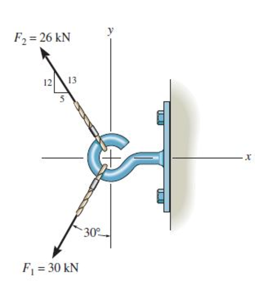
Chapter 2.4, Problem 53P
Express F1 and F2 as Cartesian
Expert Solution & Answer
Want to see the full answer?
Check out a sample textbook solution
Students have asked these similar questions
500
Q3: The attachment shown in Fig.3 is made of
1040 HR. The static force is 30 kN. Specify the
weldment (give the pattern, electrode
number, type of weld, length of weld, and leg
size).
Fig. 3
All dimension
in mm
30 kN
100
(10 Marks)
(read image) (answer given)
A cylinder and a disk are used as pulleys, as shown in the figure. Using the data
given in the figure, if a body of mass m = 3 kg is released from rest after falling a
height h 1.5 m, find:
a) The velocity of the body.
b) The angular velocity of the disk.
c) The number of revolutions the cylinder has made.
T₁
F
Rd =
0.2 m
md =
2 kg
T
T₂1
Rc = 0.4 m
mc = 5 kg
☐ m = 3 kg
Chapter 2 Solutions
INTERNATIONAL EDITION---Engineering Mechanics: Statics, 14th edition (SI unit)
Ch. 2.3 - Then establish the triangle rule, where FR = F1 +...Ch. 2.3 - Then establish the triangle rule to show FR = FU +...Ch. 2.3 - Determine the magnitude of the resultant force...Ch. 2.3 - Determine the magnitude of the resultant force....Ch. 2.3 - Determine the magnitude of the resultant force and...Ch. 2.3 - Resolve the 30-lb force into components along the...Ch. 2.3 - Resolve this force into components acting along...Ch. 2.3 - along the v axis. Prob. F2-6Ch. 2.3 - If = 60 and F = 450 N, determine the magnitude of...Ch. 2.3 - If the magnitude of the resultant force is to be...
Ch. 2.3 - Determine the magnitude of the resultant force FR...Ch. 2.3 - Determine the magnitudes of the two components of...Ch. 2.3 - Solve with F = 350 lb. Prob. 2-4/5Ch. 2.3 - Determine the magnitude of the resultant force FR...Ch. 2.3 - Resolve the force F1 into components acting along...Ch. 2.3 - Resolve the force F2 into components acting along...Ch. 2.3 - If the resultant force acting on the support is to...Ch. 2.3 - Determine the magnitude of the resultant force and...Ch. 2.3 - If = 60, determine the magnitude of the resultant...Ch. 2.3 - Also, what is the magnitude of the resultant...Ch. 2.3 - Resolve this force into two components acting...Ch. 2.3 - Determine the magnitude of F and its component...Ch. 2.3 - Determine the magnitude of F and its direction ....Ch. 2.3 - Determine the required angle (0 45) and the...Ch. 2.3 - Determine the magnitude and direction of the...Ch. 2.3 - Determine the magnitude and direction of the...Ch. 2.3 - What is the component of force acting along member...Ch. 2.3 - Take = 30. Probs. 2-19/20Ch. 2.3 - FR measured counterclockwise from the positive x...Ch. 2.3 - Solve I by first finding the resultant F = F2 + F3...Ch. 2.3 - If F1 = 400 N and F2 = 600 N, determine the angle...Ch. 2.3 - If their lines of action are at an angle apart...Ch. 2.3 - If F1 = 30 lb and F2 = 40 lb, determine the angles...Ch. 2.3 - Determine the magnitude and direction of FA SO...Ch. 2.3 - Determine the magnitude and direction, measured...Ch. 2.3 - What is the minimum magnitude of FR?Ch. 2.3 - directed along the positive x axis, determine the...Ch. 2.3 - If FB = 3 kN and = 45, determine the magnitude of...Ch. 2.3 - If the resultant force of the two tugboats is...Ch. 2.4 - Resolve each force acting on the post into its x...Ch. 2.4 - Determine the magnitude and direction of the...Ch. 2.4 - Determine the magnitude of the resultant force...Ch. 2.4 - determine the magnitude of F and its direction ....Ch. 2.4 - If the magnitude of the resultant force acting on...Ch. 2.4 - Determine the magnitude of the resultant force and...Ch. 2.4 - Determine the magnitude of the resultant force and...Ch. 2.4 - Determine the magnitude of the resultant force and...Ch. 2.4 - Resolve F1 and F2 into their x and y components.Ch. 2.4 - Determine the magnitude of the resultant force and...Ch. 2.4 - Resolve each force acting on the gusset plate into...Ch. 2.4 - Determine the magnitude of the resultant force...Ch. 2.4 - Express each of the three forces acting on the...Ch. 2.4 - Determine the x and y components of F1 and F2....Ch. 2.4 - Determine the magnitude of the resultant force and...Ch. 2.4 - Determine the magnitude of the resultant force and...Ch. 2.4 - Express F1, F2, and F3 as Cartesian vectors.Ch. 2.4 - Determine the magnitude of the resultant force and...Ch. 2.4 - Determine the magnitude of the resultant force and...Ch. 2.4 - Determine the magnitude and direction of the...Ch. 2.4 - Determine the magnitude and orientation of FB so...Ch. 2.4 - measured counterclockwise from the positive y...Ch. 2.4 - Prob. 48PCh. 2.4 - Prob. 49PCh. 2.4 - Express F1, F2, and F3 as Cartesian vectors.Ch. 2.4 - Determine the magnitude of the resultant fore and...Ch. 2.4 - Show that the resultant force is zero. Prob. 2-52Ch. 2.4 - Express F1 and F2 as Cartesian vectors.Ch. 2.4 - Determine the magnitude of the resultant force and...Ch. 2.4 - What is the magnitude of the resultant force?...Ch. 2.4 - If the magnitude of the resultant force acting on...Ch. 2.4 - Set = 30. Probs. 2-56/57Ch. 2.4 - Determine the magnitude and direction of F so...Ch. 2.4 - Prob. 59PCh. 2.6 - Show , , . a) F = {50i + 60j 10k} kN b) F = {40i ...Ch. 2.6 - In each case, establish F as a Cartesian vector,...Ch. 2.6 - Set up the calculation used to find the magnitude...Ch. 2.6 - Determine the coordinate direction angles of the...Ch. 2.6 - Express the force as a Cartesian vector. Prob....Ch. 2.6 - Express the force as a Cartesian vector. Prob....Ch. 2.6 - Express the force as a Cartesian vector. Prob....Ch. 2.6 - Express the force as a Cartesian vector. Prob....Ch. 2.6 - Determine the resultant force acting on the hook....Ch. 2.6 - Determine the magnitudes of the x, y, z components...Ch. 2.6 - If the magnitude of F is 80 N, and = 60 and =...Ch. 2.6 - The component of F in the x-y plane is 7 kN. Prob....Ch. 2.6 - Determine the magnitude and coordinate direction...Ch. 2.6 - Specify the coordinate direction angles of F1 and...Ch. 2.6 - Express each force in Cartesian vector form and...Ch. 2.6 - Determine the coordinate direction angles of F1....Ch. 2.6 - Determine the magnitude and coordinate direction...Ch. 2.6 - Determine the magnitude and coordinate direction...Ch. 2.6 - Determine the magnitude and coordinate direction...Ch. 2.6 - Determine the magnitude and coordinate direction...Ch. 2.6 - Note that F1 lies in the x-y plane.Ch. 2.6 - If the resultant force FR has a magnitude of 150...Ch. 2.6 - Express each force in Cartesian vector form.Ch. 2.6 - Determine the magnitude and coordinate direction...Ch. 2.6 - Express each force as a Cartesian vector.Ch. 2.6 - Determine the resultant of the two forces and...Ch. 2.6 - Determine the magnitude and coordinate direction...Ch. 2.6 - Prob. 78PCh. 2.6 - Determine the coordinate direction angles of the...Ch. 2.6 - Express each force in Cartesian vector form and...Ch. 2.6 - If the coordinate direction angles for F1 are 3 =...Ch. 2.6 - If the coordinate direction angles for F1 are 3 =...Ch. 2.6 - If the direction of the resultant force acting on...Ch. 2.6 - Prob. 84PCh. 2.6 - If = 75, determine the magnitudes of F and Fy....Ch. 2.8 - In each case, establish a position vector from...Ch. 2.8 - In each case, express F as a Cartesian vector....Ch. 2.8 - Express the position vector rAB in Cartesian...Ch. 2.8 - What is the angle ? Prob. F2-20Ch. 2.8 - Prob. 21FPCh. 2.8 - Express the force as a Cartesian vector. Prob....Ch. 2.8 - Determine the magnitude of the resultant force at...Ch. 2.8 - Determine the resultant force at A. Prob. F2-24Ch. 2.8 - Determine the length of the connecting rod AB by...Ch. 2.8 - Express force F as a Cartesian vector; then...Ch. 2.8 - Express each of the forces in Cartesian vector...Ch. 2.8 - If F = {350i 250j 450k} N and cable AB is 9 m...Ch. 2.8 - Prob. 90PCh. 2.8 - If z = 5 m, determine the location +x, +y of point...Ch. 2.8 - Express each of the forces in Cartesian vector...Ch. 2.8 - If FB = 560 N and FC = 700 N, determine the...Ch. 2.8 - If FB = 700 N, and FC = 560 N, determine the...Ch. 2.8 - Express each force as a Cartesian vector. Prob....Ch. 2.8 - Represent each force as a Cartesian vector. Probs....Ch. 2.8 - Determine the magnitude and coordinate direction...Ch. 2.8 - Express the force as a Cartesian vector. Prob....Ch. 2.8 - Express this force as a Cartesian vector acting on...Ch. 2.8 - Determine the magnitude and coordinate direction...Ch. 2.8 - Represent each force as a Cartesian vector and...Ch. 2.8 - The anticipated loading in two of the struts is...Ch. 2.8 - Determine the magnitude and coordinate direction...Ch. 2.8 - If the force in each cable tied to the bin is 70...Ch. 2.8 - Due to symmetry, the tension in the four cables is...Ch. 2.9 - Do not calculate the result. Prob. P2-8Ch. 2.9 - P2.9. In each case, set up the dot product to find...Ch. 2.9 - Determine the angle between the force and the...Ch. 2.9 - Determine the angle between the force and the...Ch. 2.9 - Determine the angle between the force and the...Ch. 2.9 - Determine the projected component of the force...Ch. 2.9 - Find the magnitude of the projected component of...Ch. 2.9 - Determine the components of the force acting...Ch. 2.9 - Determine the magnitudes of the components of the...Ch. 2.9 - Express the force F in Cartesian vector form if it...Ch. 2.9 - Express force F in Cartesian vector form if point...Ch. 2.9 - If the force in each chain has a magnitude of 60...Ch. 2.9 - If the resultant force at O has a magnitude of 130...Ch. 2.9 - Determine the length of the chain, and express the...Ch. 2.9 - Determine the length of the cable and express the...Ch. 2.9 - Prob. 112PCh. 2.9 - Determine the magnitudes of the components of F =...Ch. 2.9 - Determine the angle between the two cables. Prob....Ch. 2.9 - Determine the magnitude of the projection of the...Ch. 2.9 - Determine the angle between the y axis of the...Ch. 2.9 - Determine the magnitudes of the projected...Ch. 2.9 - Determine the angle between cables AB and AC....Ch. 2.9 - Prob. 119PCh. 2.9 - Determine the magnitude of the projected component...Ch. 2.9 - Determine the angle between the two cables...Ch. 2.9 - Determine the angle between the cables AB and AC....Ch. 2.9 - Determine the magnitude of the projected component...Ch. 2.9 - Determine the magnitude of the projected component...Ch. 2.9 - Determine the magnitude of the projection of force...Ch. 2.9 - Determine the magnitude of the projected component...Ch. 2.9 - Determine the angle between pipe segments BA and...Ch. 2.9 - Prob. 128PCh. 2.9 - Determine the magnitude of the projected component...Ch. 2.9 - Determine the angles and made between the axes...Ch. 2.9 - Prob. 131PCh. 2.9 - Express this component as a Cartesian vector....Ch. 2.9 - Prob. 133PCh. 2.9 - Prob. 134PCh. 2.9 - Determine the magnitudes of the components of the...Ch. 2.9 - Determine the magnitudes of the projected...Ch. 2.9 - Prob. 137PCh. 2.9 - Determine the angle between the two cables....Ch. 2.9 - Express the result as a Cartesian vector.Ch. 2.9 - Determine the magnitude of the resultant force FR...Ch. 2.9 - Resolve F into components along the u and v axes...Ch. 2.9 - Determine the magnitude of the resultant force...Ch. 2.9 - Prob. 4RPCh. 2.9 - The cable attach to the tractor at B exerts a...Ch. 2.9 - Prob. 6RPCh. 2.9 - Determine the angle between the edges of the...Ch. 2.9 - Determine the projection of the force F along the...
Knowledge Booster


Learn more about
Need a deep-dive on the concept behind this application? Look no further. Learn more about this topic, mechanical-engineering and related others by exploring similar questions and additional content below.Similar questions
- (read image) (answer given)arrow_forward11-5. Compute all the dimensional changes for the steel bar when subjected to the loads shown. The proportional limit of the steel is 230 MPa. 265 kN 100 mm 600 kN 25 mm thickness X Z 600 kN 450 mm E=207×103 MPa; μ= 0.25 265 kNarrow_forwardT₁ F Rd = 0.2 m md = 2 kg T₂ Tz1 Rc = 0.4 m mc = 5 kg m = 3 kgarrow_forward
- 2. Find a basis of solutions by the Frobenius method. Try to identify the series as expansions of known functions. (x + 2)²y" + (x + 2)y' - y = 0 ; Hint: Let: z = x+2arrow_forward1. Find a power series solution in powers of x. y" - y' + x²y = 0arrow_forward3. Find a basis of solutions by the Frobenius method. Try to identify the series as expansions of known functions. 8x2y" +10xy' + (x 1)y = 0 -arrow_forward
- Hello I was going over the solution for this probem and I'm a bit confused on the last part. Can you please explain to me 1^4 was used for the Co of the tubular cross section? Thank you!arrow_forwardBlood (HD = 0.45 in large diameter tubes) is forced through hollow fiber tubes that are 20 µm in diameter.Equating the volumetric flowrate expressions from (1) assuming marginal zone theory and (2) using an apparentviscosity for the blood, estimate the marginal zone thickness at this diameter. The viscosity of plasma is 1.2 cParrow_forwardQ2: Find the shear load on bolt A for the connection shown in Figure 2. Dimensions are in mm Fig. 2 24 0-0 0-0 A 180kN (10 Markarrow_forward
- determine the direction and magnitude of angular velocity ω3 of link CD in the four-bar linkage using the relative velocity graphical methodarrow_forwardFour-bar linkage mechanism, AB=40mm, BC=60mm, CD=70mm, AD=80mm, =60°, w1=10rad/s. Determine the direction and magnitude of w3 using relative motion graphical method. A B 2 3 77777 477777arrow_forwardFour-bar linkage mechanism, AB=40mm, BC=60mm, CD=70mm, AD=80mm, =60°, w1=10rad/s. Determine the direction and magnitude of w3 using relative motion graphical method. A B 2 3 77777 477777arrow_forward
arrow_back_ios
SEE MORE QUESTIONS
arrow_forward_ios
Recommended textbooks for you
 International Edition---engineering Mechanics: St...Mechanical EngineeringISBN:9781305501607Author:Andrew Pytel And Jaan KiusalaasPublisher:CENGAGE L
International Edition---engineering Mechanics: St...
Mechanical Engineering
ISBN:9781305501607
Author:Andrew Pytel And Jaan Kiusalaas
Publisher:CENGAGE L
How to balance a see saw using moments example problem; Author: Engineer4Free;https://www.youtube.com/watch?v=d7tX37j-iHU;License: Standard Youtube License